Apparently there is a gaping hole in my understanding of negative feedback! Normally when you apply voltage feedback, the output impedance will fall by the same factor as the gain reduction.
Yesterday I was testing a simple 6L6 PP amp, and measured the output impedance to be 170 ohms. Then I applied about 6dB feedback. THD fell by half as you would expect, but the output impedance fell to 16 ohms!
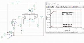
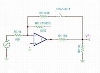
So I created a very simple circuit model to see if I was going mad, and sure enough I get basically the same result. What is happening here? Why is the output impedance changing by a factor of ten? I feel like I'm missing something very obvious!
Frequency response shown below, indicating 6dB of feedback. 6L6s are biased to 42mA cathode current.
Yesterday I was testing a simple 6L6 PP amp, and measured the output impedance to be 170 ohms. Then I applied about 6dB feedback. THD fell by half as you would expect, but the output impedance fell to 16 ohms!
So I created a very simple circuit model to see if I was going mad, and sure enough I get basically the same result. What is happening here? Why is the output impedance changing by a factor of ten? I feel like I'm missing something very obvious!
Frequency response shown below, indicating 6dB of feedback. 6L6s are biased to 42mA cathode current.
Attachments
The open-loop impedance only depends on the pentode's ra; and since this has no relationship to the feedback circuit, the prediction is not valid.the output impedance will fall by the same factor as the gain reduction.
Going from open-loop to closed-loop, the reduction is from an unpredictable/uncontrolled value of Zo, so how can we talk about dBs (ratio) ?
However, as soon as the loop is closed, you can start talking about ratios:
If we leave the op-amp in-circuit, and increase the closed-loop gain in steps, we can expect the output impedance to behave as predicted, I suspect.
The FB ratio has never been 6 dB and it isn't voltage fb either.
The (-) input of the opamp is a virtual ground or current summing point. The opamp's output counteracts the input signal thru it's fb resistor such that the sum of both currents stays zero. Now the 100k gfb resistor injects an additional current into that node messing up the local fb around the opamp ...
The (-) input of the opamp is a virtual ground or current summing point. The opamp's output counteracts the input signal thru it's fb resistor such that the sum of both currents stays zero. Now the 100k gfb resistor injects an additional current into that node messing up the local fb around the opamp ...
OK working through the maths it turns out that output impedance drops by more than the gain reduction when the loop gain is small, as it normally is in a tube output stage. This is pleasing as it means we don't need as much feedback around a pentode output stage, to acheive a half-decent damping factor, as I initially assumed. You live and learn!

Aren't you mixing up loop gain with and without load? Loop gain without load will be much more than with load.
In his book "Physik der Elektrogitarre" Prof. Manfred Zollner shows output impedance results (measured and calculated) for a few guitar amps. Also gives the formulas.OK working through the maths it turns out that output impedance drops by more than the gain reduction when the loop gain is small, as it normally is in a tube output stage.
https://gitec-forum-eng.de/wp-content/uploads/2019/02/poteg-10-05-6-negative-feedback.pdf
E.g. Fender Super Reverb circuit Zo = 180 Ohm without NFB and 18 Ohm (at 8Ohm output) with NFB.
Interesting to note: The open loop gain of a tube amp (strongly) varies with the load.
The "actual" or "inner" open loop gain (without load) might be 20 times larger than with designated load.
This roughly corresponds to the ra/Za ratio (its actually a voltage divider effect).
Edit: Missed MarcelvdG's post above.
Last edited:
Yes I was! No wonder I was confused.Aren't you mixing up loop gain with and without load?
While i understand a little lot of this and a lot is over my head, its awesome to see a well known vet still asking questions and learning. Great inspiration
Indeed even cleanest guitar amps have always DF way below 1.E.g. Fender Super Reverb circuit Zo = 180 Ohm without NFB and 18 Ohm (at 8Ohm output) with NFB.
I hope to have time, during Christmas break, to try an idea I had for a clean guitar amp: UL to linearize curves of the EL34, then apply positive shunt feedback to the phase splitter to have CCS-like load and lower DF at guitarland levels.
Excuse me, why?Indeed even cleanest guitar amps have always DF way below 1.
Walter
@waltube because instrument amps, but specially guitar amps, use the impedance of the speaker to equalize the sound of the power amp. Boutique amps have three controls on feedback: the gnfb that sets the general amount of feedback of the amp, so the amount and ratio of harmonics at a specific volume, then there are two controls that shunts the feedback to ground at low frequencies around 80-200 Hz (to increase bass where the speaker impedance goes up) and at high frequencies (few kHz) to increase presence. Commercial amps have at least the Presence control, some have Presence and Depth, few have all three controls.
I am not so in deep with instrument amp but normally they have a pentode connection and it is difficult to understand how they have a DF less than 1 also seeing the ratio of the output transformer. Maybe theu use a huge FBbecause instrument amps, but specially guitar amps, use the impedance of the speaker to equalize the sound of the power amp
Walter
probably I haven't write right the concept or you haven't undestand.ehm… a low DF means an high output impedance, that’s exactly what a pentode gives on a low Raa primary with LOW-to-NO gnfb.
I re-read my post, please do the same
And I know exactly what is DF
Walter
I re-read my post, please do the same
And I know exactly what is DF
ok… but then why you wrote:
In this part above of your post you say it is difficult that a pentode connected on a low Raa output transformer (just to give an example: a pair of EL34 in pentode in PP on a 3.4 kOhm Raa) can have a DF lower than 1. But this is exactly what it is expected from this configuration. Then you say:instrument amp have a pentode connection and it is difficult to understand how they have a DF less than 1 also seeing the ratio of the output transformer.
Here again you write the opposite of what happens in reality: a huge amount of feedback gives a higher DF amp, not lower as you said. It is exactly the opposite of what you wrote.Maybe theu use a huge FB
I think you just confused DF and Zout of the output stage, that are indeed inversely proportional.
I know.I think you just confused DF and Zout of the output stage, that are indeed inversely proportional.
My post was not clear, my error.
I confused Zout ad DF, stupid exchange.
One of the goal of my stuff with tubes is always get a decent DF !!!
Walter
- Home
- Amplifiers
- Tubes / Valves
- Output impedance falls by more than the feedback factor?