I would stick with Mean-Well. If you buy at Mouser, you will get a product that complies with your local regulations.
The kind of supply you linked is quite limited in power output. You will need at least one for any Mono TPA3255.
I would not get that type of closed supply. They get real hot under load.
If possible, use a supply with high overload. This Meanwell has only 350 Watt, but will do up to 200% for a short time. Which is what audio usualy is. You don't pull constant 500 Watt, but very short burst's.
https://www.meanwell.com/webapp/product/search.aspx?prod=LRS-350N2
If possible, buy some ferrit rings to install around power input and output wires. If you have more than on amp, better take one PS each, as they do not like to be feed by one large PS.
I got such a PS from another large Chinese manufacturer, the dam thing makes any radio in a 5 meter radius buzz at full volume. Next time I buy Meanwell again, they are a little cleaner. We want to use them for audio...

Thanks @Turbowatch2 🙂 Yes, I'm a big fan of the Meanwell industrial supplies also...I've got a couple of the basic LRS-350 (non N2) which I've been very happy with on my DIY sylph and other TI boards. I wasn't aware of the N2 peak power version until now actually so that's a great find, thanks. The issue is that while the caged supplies are certified to comply with AS/NZS 62368.1 once you wire them into case my understanding is that then requires a separate inspection and certification which is no small exercise and not within the means of a humble DIYer. For DIY at home, where the maker is the only person operating the equipment it's obviously no problem but if the amplifier was ever to be used in a public place I'd always want the reassurance of full electrical compliance. However if external supplies really are not optimal perhaps I just need to rethink the exercise - in fact I just rechecked that meanwell external brick I linked and it actually lacks the relevant AS/NZS compliance so that wouldn't be of much help to me anyway.
Last edited:
Hi everyone!
It's been a while since I don't post here, I recently got a 3255 based Amp, the Aiyima A07 Max.
I went around testing it, changed the input caps to 10uF FGs and some of the filtering caps for metal film ones.
It sounds kinda fine, but the moment I tried using my FiiO BR13 EQ to up the bass a bit as I mostly listen in lower volumes, I noticed distortion.
I then used my very cheap DSO150 scope on the outputs and noticed a constant signal between 47~49khz with quite a bit of power running through it.
I've tried just about everything, used my Meanwell 24V from the 3116, tried using other power sockets, but that constant signal sits there.
I have asked this in the ASR forums, but I am getting a bit worried, I haven't used the amp since I noticed it in fear of possibly damaging my speakers (sorry, I am not very knowledgeable in the field).
I mainly use it with a Meanwell LRS350 48V set to it's minimum voltage (42V). Both powersupplies I tested gave me the same result. Measuring my TPA3116 and a linear PSU based LM3886 does not show that type of interference/signal.
I've tried changing back to the old electrolytic capacitors, tried using other dac as well, the signal stays there, even without anything plugged to it besides power. It begins as soon as the relay kicks in.
Anyone knows what could be causing this? Is it something I should be worried about?
Any input is very appreciated, thanks!

That might be what my 'cheaposcope' is picking up and showing as 47~48khz! Thanks @MRamone !
Did you change the input capacitors on yours, by any chance? I have tried 10uF capacitors in place for those 4.7uF ELNAs, it does improve the signal overall, but I guess the way they made the input/op amp circuit 10uF might be too much for it to handle. The 4.7uFs makes it seem like there's less bass than it should to me, and the 10uFs can't handle if I boost frequencies on the FiiO BR13 I have...
I ended up getting frustrated with the amp and got a Fosi V3, waiting for it to arrive.
hii.. i have this Amp TPA3251 by Vire.. its very cheap on my Local Online shop Indonesia, under $10 🤣 .. i dont know seller wrong price or not 🤣
but strangely output component not completely .. should i add component manually (1nF, 10nF and 3.3Ohm) like datasheet??
will be making big impact if i completing component?? because im now listen music using this amplifier and its sound normally 😆
but strangely output component not completely .. should i add component manually (1nF, 10nF and 3.3Ohm) like datasheet??
will be making big impact if i completing component?? because im now listen music using this amplifier and its sound normally 😆
Last edited:
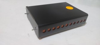
Got this amp for under 40 buck including shipment! must be my lucky day.... the previous owner got troubled with occasionally shutdown after a minutes play music, so my suspect is that the amp is over heat and enter the protect mode. Try with 36 v and everything run smooth....i dont realy understand why fosi ship a 48v adaptor for this really small amp...
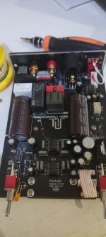
Try open the case later for re pasting the thermal compound and see anything i can upgrade. From the internet's picture i think to swap the main capacitor from 2200uf nichicon pw to 1000uf panasonic FM+ 1uf ceramic capacitor for lower esr, changed ne5532p opamp to 5532ap (better distortion), and maybe swap the elco capacitor in near opamp to 105c rate, but for now im really happy what this amp sound...
Try open the case later for re pasting the thermal compound and see anything i can upgrade. From the internet's picture i think to swap the main capacitor from 2200uf nichicon pw to 1000uf panasonic FM+ 1uf ceramic capacitor for lower esr, changed ne5532p opamp to 5532ap (better distortion), and maybe swap the elco capacitor in near opamp to 105c rate, but for now im really happy what this amp sound...
Attachments
You could just try taking it out of its case and see if then runs fine with the 48V brick. If that work you might just try adding vent holes in the case, directly above the heatsink. Nuthin complicated first
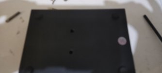
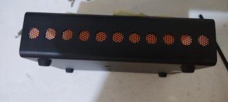
Well the problem is, the case is a heatsink itself for this amp so removing the case will also removing the heatsink (the chip is bolt directly to bottom of the aluminium case). Many user of this amp has fried their amp or the case become so hot to handle
Having the tpa3255 heatsinked to the case bottom is a great way to heatsink it. If the case is too small for the heat you need to dissipate just stick on a finned CPU cooler. Elevate the amp on tall legs to cool the bottom or flip upside down. On my Warp-1 amp design the bottom is a 5mm thick aluminum plate capable of dissipating 30W. At 90% efficiency, that means the chip could be pushed to 300W output at thermal limit.
Yes it will do, put this upside down and adding fin is a good idea.... but i got this amp because the thermal protection problem from previous owner and many others fry their v3 mono amp as well, so i doubt that this is a good amp cooling design for 48v. It has small internal plate from chip to connected with the case, but between the plate and case has no thermal paste, some owner of this amp even feel the case is cold to touch before it failed (that mean the heat not transfered good enough to the case). Anyway I'll better stick with 36v, this amp is for my center channel duty anyway....i route my 80hz to main speaker and all 40hz channel to sub, so don't need the bass too much, just a good and clean freq from 80hz above....
Do you have pics of this?Well the problem is, the case is a heatsink itself for this amp so removing the case will also removing the heatsink (the chip is bolt directly to bottom of the aluminium case). Many user of this amp has fried their amp or the case become so hot to handle
Very insightful observation of the thin alloy case conundrum I've also seen. If indeed it's an alloy case, then something is amiss as it should be cooling ok.
Aluminum has a much higher conduction coefficient and higher specific heat than steel. A thicker alloy housing would be a much better substrate to attach the 3251/5 chip to if a large alloy finned heat sink cannot be incorporated.
Last edited:
The chip is bolt under the aluminium plate, than when inserting the board to the case we must bolting the case to the aluminium plate from the buttom. The case then act like heatsink release the heat from the body. Well thats the theory, in reality sometimes it doesn't work, there's no thermal paste between the plate or maybe the gap of the plate and the case is to narrow...i dunno, but my amp suffer from heat problem for sure because when i play the amp in 36v everything is fine. Sorry for my bad english its not my main languages
Attachments
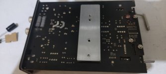
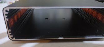
Those pics explain it all. The thin alloy case itself is not interfaced with the heat block properly. Hard to believe no thermal paste was added. To improve the heat transfer further, you could even remove/polish the anodization from the case where it mates with the heat block. Also check that heat block is polished where it interfaces with the chip.
One would have thought, because heat rises, they would have designed the circuit board to mount inside the case with the metal bar at the top of the unit instead of the bottom. As suggested, put thermal paste in between and maybe even run the amp turned upside down so the heat is at the top of the unit?
To exacerbate the problem, the manufacturer didn't bother to include vent ports to the bottom, trapping the heat within the small air space between case bottom and PCB, effectively baking it. Last time I checked, electronics and circuits perform to an entirely different spec when subjected to high temps.
Thermal paste would work well but you don’t want the thermal pad of the TPA3255 chip touching the chassis ground. That would make it susceptible to noise and hum. The thermal pad should be electrically isolated but thermally conductive with the chassis. I use a silicone heat sink pad between the thermal block and chassis and paste between the TPA3255 and the thermal block. Without the paste it is very bad because the heat flux is huge. Up to 10W or so over a tiny 5mm x 12mm area.The chip is bolt under the aluminium plate, than when inserting the board to the case we must bolting the case to the aluminium plate from the buttom. The case then act like heatsink release the heat from the body. Well thats the theory, in reality sometimes it doesn't work, there's no thermal paste between the plate or maybe the gap of the plate and the case is to narrow...i dunno, but my amp suffer from heat problem for sure because when i play the amp in 36v everything is fine. Sorry for my bad english its not my main languages
I have a video showing how I connect the thermal block on my amp to the chassis using both paste and silicone thermal pad. This part starts at about 2min in if you want to skip the preliminary setup stuff specific to my TPA3255 amp design.
Last edited:
- Home
- Amplifiers
- Class D
- TPA3255 - all about DIY, Discussion, Design etc