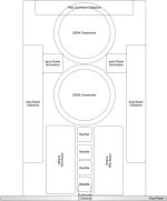
Just pulled the trigger on a Mini Dissipante 3U * 400mm chassis, with custom cutouts for the front and rear panels, and pre-drilled heatsink holes for some of the amp boards I've been wanting to build. As you can see from the mockup, it'll be a tight fit to squeeze in two 200VA transformers and the PSU boards, but I plan to stack the PSUs on top of the transformers with 70mm standoffs. I may have to fall back to a single, 400VA transformer, but hopefully not. Parts list then build notes to follow.

Attachments

Parts list:
- 2 x 200VA Transformer, from Antek
- Dual NP bipolar power supply kit, from DiyAudioStore
- Set gold binding posts, from DiyAudioStore
- Keratherm, from DiyAudioStore
- Neutrik XLR and RCA connectors, from Markertek
- Twisted, Shielded 22AWG pair, from Markertek (mainly to qualify for free shipping 🙂)
- Non-switched, fused IEC power-entry connector, from Digikey
- 20 x 10-15AWGx1/4" quick-connect tabs for rectifier leads, fromDigikey
- 10 x 70mm M3 aluminum standoffs, from AliExpress
- 22mm metal pushbuttons (one black, one brushed aluminum) from AliExpress
- Mini Dissipante 3U 400mm 10mm Black front panel, with base plate, feet, and custom drilling (sweet 20% Black Friday deal!)
- 14 AWG solid core for IEC-to-pushbutton AC, DC power distribution, and output signal
- 18-22 AWG solid core elsewhere
Last edited:
Heatsink holes aligned so that power transistors mount 1/3 of the way up from the bottom:

3mm holes for LEDs, and 22mm hole for DPST pushbutton:

Neutrik connector cutouts for either XLR or RCA jacks, binding posts, and IEC power-entry module:

3mm holes for LEDs, and 22mm hole for DPST pushbutton:
Neutrik connector cutouts for either XLR or RCA jacks, binding posts, and IEC power-entry module:
It seems your goal is dual mono.
The Antek AS-2218 is shown as 2.2" tall. The heatsinks for a 3U are ~4.75" tall. If you intend to use the standard perforated base plate in the chassis, my guess is that you will not fit the toroids in a stacked configuration, but I didn't measure precisely, and I've never tried that exact configuration. You also need to consider that the mounting bolt will stick up a bit beyond the top of the toroid(s) and you DO NOT want the mounting bolt touching the top plate, or you'll need to take other precautions to avoid a shorted turn.
tl;dr - If you're using the perforated baseplate, I'd count on losing ~0.5" of vertical working space.
So... that's a long way of saying... LOVE the design work, but my experience and some back of the matchbook math indicate you may be better off with a single toroid mounted up front (away from the input / output wiring) and going with a standard single PSU. You may also find that you can fit two 200VA side by side at the front of the chassis, and your PSU boards just in front of those (toward the middle).
You may be able to stack your PSU boards above each other vs. over the toroids, or fit them side-by-side.
Good luck! Can't wait to see how it evolves.
Edited to add - I saw you're using the PSU kit from the store. Those (built) are a shade < 1.25" tall. So, you may be able to fit them over a toroid, and you should definitely be able to stack the PSUs (if that's what you want to do). They're nice and compact. Sorry for not seeing that earlier. Edited above for clarity knowing you're using those PSU boards.
Also - What width for the chassis do you have in your software? It looks 'narrow' to me.... but... never trust my scaling / vision.
Last edited:
Appreciate another pair of eyes on this! So I too started with some back-of-the-envelope calcs, and ended up drafting (with OmniGraffle) as it was so close. The new, kit-based bipolar PSU boards measure 30mm to the top of the caps, and the 200VA toroids stand a little over 60mm tall. The usable vertical space in the chassis with baseplate installed is 110mm, so cautiously optimistic that this stacking scheme will work.So... that's a long way of saying... LOVE the design work, but my experience and some back of the matchbook math indicate you may be better off with a single toroid mounted up front (away from the input / output wiring) and going with a standard single PSU. You may also find that you can fit two 200VA side by side at the front of the chassis, and your PSU boards just in front of those (toward the middle).
The other scheme that I considered involved standing the PSU boards up vertically. Didn't like the front pushbutton placement as well, and I would have had to mount the boards to the bottom coverplate directly for them to fit (120mm).
Useful internal width is 250mm.Also - What width for the chassis do you have in your software? It looks 'narrow' to me.... but... never trust my scaling / vision.
🤞🏾Good luck! Can't wait to see how it evolves.

Good thought. Might have been able to get that to work, but I'd have had to forgo a baseplate altogether to even come close.Have you considered mounting the psu pcb vertically side to side?
Attachments
I'd say that latest arrangement looks much better than previous. MiniDissipante 3U is my favorite form factor from Modushop, but it is indeed tight. Without the perforated baseplate, you'll likely need a fifth foot in the middle for support. Careful AC vs. DC wire routing/dressing will be important.
Another idea/implementation, beautifully executed by member stretchneck:
Best,
Anand.
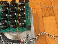
686 build complete... I'm rather chuffed with it. Built using Tom's layout as available for download from the product page, but with dual-mono Toroidy Supremes in a 'Power cube' format using maker beam. No corners cut, and some unique features. Will post review / comparisons in due course.
Loving the dual colour LED on the font panel.
Thanks Tom for your support and products!


Loving the dual colour LED on the font panel.
Thanks Tom for your support and products!
Best,
Anand.
Beautifully executed, indeed! Is that a 4U chassis?Another idea/implementation, beautifully executed by member stretchneck:
Agreed, I'd prefer the symmertric front panel. Hopefully stacking will work, because wiring would be more straightforward.I'd say that latest arrangement looks much better than previous. MiniDissipante 3U is my favorite form factor from Modushop, but it is indeed tight. Without the perforated baseplate, you'll likely need a fifth foot in the middle for support. Careful AC vs. DC wire routing/dressing will be important.
I am not speaking from personal experience, merely from what I have read on here. However, these are well trodden paths so there is some certainty about the result. I apologise of this is old news...
A couple of things:
-Per Zenmod, use the perforated baseplate `lip up' and space the bottom cover down off the heat sinks for a little more internal height
Keep the transformers away from the input end of the boards and as much as possible keep ALL of the AC away from the input end of the boards
-> I interpret that to mean that the transformers should be on the centerline of the case and at the end furthest away from the inputs. Logically this means the bridge rectifiers and CRC (or CLC), should also be on the centerline of the box as this is the location furthest from each board.
Note the differentiation between `safety earth' and signal ground and the use of ground lift, small signal routing, twisting of wire pairs, etc.
Over recent years/months I have downloaded some useful information which I attach here. If links (as opposed to pdfs), are easier these documents can be readily found via google. I apologise in advance for not giving proper acknowledgement to the authors, none of this is my work and all of it deserves study.
Attachments
-
ilimzns-Excellent-Posts-on-Ground-Loops.pdf225 KB · Views: 72
-
Reducing-Loop-Area-in-Audio-Amplifiers.pdf190.3 KB · Views: 68
-
More-Notes-On-Amplifier-Hum-Problems.pdf801.8 KB · Views: 51
-
How-to-wire-up-a-Power-Amplifier_Updated.pdf826 KB · Views: 75
-
Ground-Loops.pdf2.8 MB · Views: 108
-
Dual-Mono-Wiring.pdf451.9 KB · Views: 82
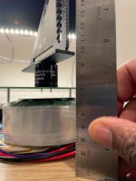
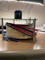
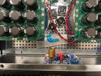
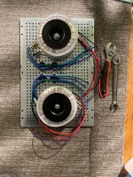
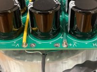
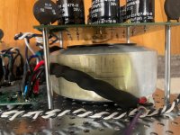
Looking good here! 70mm risers arrived, and I'm measuring the top of the PSU board sitting just shy of 100mm above the deck as expected. And plenty of clearance above the transformer too. All I need now is the chassis ...
Attachments
FedEx is poised to deliver my chassis tomorrow, a day late, so time to get stuffing here. PSU board kit goes together super fast, especially with the standoffs installed ahead of time -- saves fiddling with the board clamp. Also, new since the last time I built one of these, are the little power-entry hookup boardlets which are a nice convenience.

I decided to go with a @Zen Mod Aleph J kit first in this build, rather than cannibalizing the boards from my F5m build. Also easy to put together, despite the relative complexity vs the F5m. Got all but the bigger caps and active devices stuffed and soldered this afternoon/evening.


I decided to go with a @Zen Mod Aleph J kit first in this build, rather than cannibalizing the boards from my F5m build. Also easy to put together, despite the relative complexity vs the F5m. Got all but the bigger caps and active devices stuffed and soldered this afternoon/evening.
LOL -- Finished soldering up the amp boards right before dinner, and chassis arrived just as we were clearing the table.

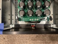
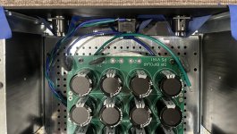
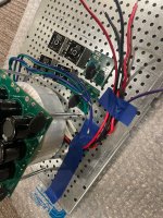
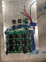
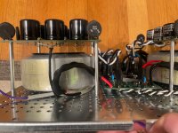
First the good news: stacked PSU/trafo combo fits comfortably, with just over a centimeter clearance. Phew.


And I got the HS hole patterns right. Also phew.

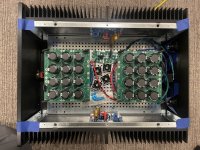
The not so good news: no cutouts in the rear panel. I'll just borrow the backpanel from my other chassis until this issue gets resolved so I don't stall out, but disappointing to have to wait a bit longer to button things up :<
I taped some of the rear connectors into place so I could get a visceral sense of the finished assembly, and also tried out the two pushbuttons for fit and finish (leaning towards the stainless over black, I think). Overally I'm pretty pleased with how this thing is shaping up.


Good place to stop for the day. Hopefully I'll get the wiring done tomorrow.
First the good news: stacked PSU/trafo combo fits comfortably, with just over a centimeter clearance. Phew.
And I got the HS hole patterns right. Also phew.
The not so good news: no cutouts in the rear panel. I'll just borrow the backpanel from my other chassis until this issue gets resolved so I don't stall out, but disappointing to have to wait a bit longer to button things up :<
I taped some of the rear connectors into place so I could get a visceral sense of the finished assembly, and also tried out the two pushbuttons for fit and finish (leaning towards the stainless over black, I think). Overally I'm pretty pleased with how this thing is shaping up.
Good place to stop for the day. Hopefully I'll get the wiring done tomorrow.
Attachments
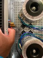
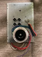
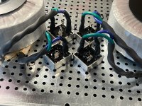
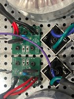
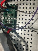
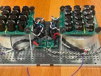
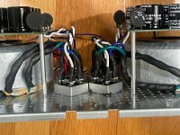
Finished up most of the AC wiring. Lots of heatshrink tubing to maintain twists in the paired leads, and to keep them as far from amp boards as possible.

Attachments
-
 IMG_4793.jpg898 KB · Views: 67
 -
 IMG_4791.jpg1.5 MB · Views: 1,436
 -
 IMG_4790.jpg1.5 MB · Views: 273
 -
 IMG_4789.jpg1.1 MB · Views: 68
 -
 IMG_4795.jpg841.1 KB · Views: 65
 -
 IMG_4796.jpg991.8 KB · Views: 70
 -
 IMG_4797.jpg906.3 KB · Views: 66
 -
 IMG_4799.jpg897.3 KB · Views: 72
 -
 IMG_4800.jpg941.3 KB · Views: 69
 -
 IMG_4788.jpg1.1 MB · Views: 67
- Home
- Amplifiers
- Pass Labs
- Dual PSU build in Mini Dissipante 3U/400mm for F5m/F4/M2x/Aleph Jzm