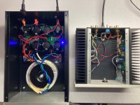
Come to think of it, I do have an extra PSU sitting around now, enough to power four ACAs. Thinking ...make outboard linear power supplies for your ACAs.
Yup, so I'd use one rail per ACA, since they don't care about absolute ground reference.That's a dual rail. The ACA needs a single rail,
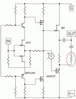
I personally don't understand negative rails relative to ground. I get that if one measures from ground to the negative rail one will read a positive potential difference, yet there are schematics like the SIT-5 that specifically show a negative rail and a ground. How is that different from a positive rail where ground is shown and ground where negative is shown.
Attachments
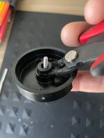
It was something I thought I bought off of Amazon but I can't find it in my purchase history. I thought I saw it listed there the other day as well but now I can't find it again. It would probably turn up under the search terms "diy aluminum amplifier project box" or some variant thereof.@ranshdow what's the enclosure for that power supply?

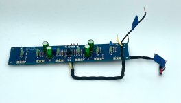
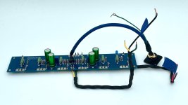
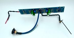
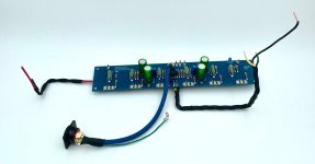
It's a hack. Mine is not delivering 24V under load (but still sounds amazing) so you may have to fuss with the right secondary voltages. Others in that thread have tried it.I would really like to hear more about these linear power supplies for the ACA.
Let me preface my response to this by saying that, as a practical matter, I'd probably never use all four rails to power ACAs (there's overkill, and then there's OVERKILL). It's more likely that I'd wire the output terminals to use just the positive rails of this PSU. Better yet, wire positive and negative rails to the connectors, and build cables that only tapped the positive pins, perhaps.personally don't understand negative rails relative to ground. I get that if one measures from ground to the negative rail one will read a positive potential difference, yet there are schematics like the SIT-5 that specifically show a negative rail and a ground. How is that different from a positive rail where ground is shown and ground where negative is shown.
Back to the negative rails thing ... maybe be the easiest way to think about this is that "ground" is an arbitrary reference. In this case, the ACA doesn't need to be referenced to the power supply ground, so it should run just fine across the -24v and ground terminals of a dual-rail supply. There is a safety concern here: if two ACA chassis referenced to different terminals of the PSU were to come into contact, there'd probably be fireworks -- that's reason enough not to do this.
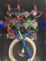
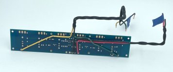
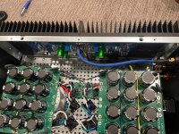
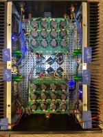
My F4 board set arrived yesterday, so I started assembling the wiring harnesses while waiting for the BOM to arrive. I'm finding that routing the heavier gauge wires underneath the amp boards makes it a lot easier to reach and adjust the biasing pots in this relatively tight chassis.
Attachments
Installed the left channel F4 board successfully last night, with a bit of fiddling and headscratching to begin with. The main dead end was attempting to follow this advice from the (generally excellent!) F4 Build Guide by @6L6:

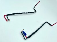
It proved impossible to align all 18 pins to their respective holes with the limited access I have alongside the PSUs. Tacking them into place on the board with some masking tape was much more successful:


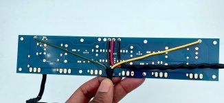
Pretty much smooth sailing after that, especially with the help of the bendy drive extension that came with my iFixit tool kit. I was also relieved to confirm that access to the trim pots is very good -- they're situated quite close to the top of the enclosure, and within the gap between the PSU stacks.

I find it helpful to bend the leads of the transistors first, and mount them (a little bit loose) to the heatsink.
It proved impossible to align all 18 pins to their respective holes with the limited access I have alongside the PSUs. Tacking them into place on the board with some masking tape was much more successful:
Pretty much smooth sailing after that, especially with the help of the bendy drive extension that came with my iFixit tool kit. I was also relieved to confirm that access to the trim pots is very good -- they're situated quite close to the top of the enclosure, and within the gap between the PSU stacks.
Attachments
I took a small-ish detour to swap out the 70mm aluminum standoffs that support the PSU boards above their transformers with a hexagonal, stainless steel set from AliExpress instead. The aluminum ones were difficult to tighten properly because of their circular profile; and also, as I discovered, their threads are relatively easy to strip.
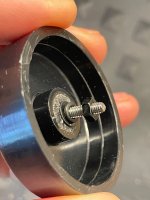
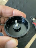
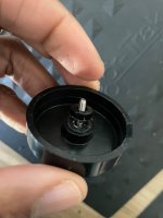
My little detour begat another detour: to find a better solution for mounting the ModuShop antivibration feet to the bottom of the chassis. The "problem" is that after screwing the feet on, the mounting screws are semi-permanently sealed in by the stick-on felt pads. I've tried gluing the screws to the feet so I can un/screw them in and out without having to peel off the felt, but it's not terribly effective. This time, I trimmed the "axle" of the feet to make room for a locking washer and nut, a much more robust solution.
My little detour begat another detour: to find a better solution for mounting the ModuShop antivibration feet to the bottom of the chassis. The "problem" is that after screwing the feet on, the mounting screws are semi-permanently sealed in by the stick-on felt pads. I've tried gluing the screws to the feet so I can un/screw them in and out without having to peel off the felt, but it's not terribly effective. This time, I trimmed the "axle" of the feet to make room for a locking washer and nut, a much more robust solution.
Attachments


- Home
- Amplifiers
- Pass Labs
- Dual PSU build in Mini Dissipante 3U/400mm for F5m/F4/M2x/Aleph Jzm