"4P1L has a fantastic set of curves, it’s extremely linear and interestingly when filaments are connected in series and with G3 at the filament center point, the mu is slightly higher (above 9) than when in wired parallel (about 8)." Ale Moglia
https://www.bartola.co.uk/valves/2013/09/29/4p1l-model-improved/
https://www.bartola.co.uk/valves/2013/09/29/4p1l-model-improved/
Most likely explained as a nonlinear increase in gm at the + end, not offset by the reduction in gm at the - end.
gm depends on anode current and Vak, so it is like operating over a wider section of the triode curves at the same time.
IOW the bias skew exaggerates gm at the ends - not likely to result in good sound!
gm depends on anode current and Vak, so it is like operating over a wider section of the triode curves at the same time.
IOW the bias skew exaggerates gm at the ends - not likely to result in good sound!
It will function..... But remember that the push pull anode currents are in opposition:Mr. Coleman...can one regulator be used for both power tubes in the Posh Pu ll amplifier? You had previously commented that two regulators should be used.
- if you connect the filaments directly across each other, there will be crosstalk corruption.
This explains why they sound best with private a regulator for each DHT.
Thanks Bela - very interesting indeed. I knew from experience that you needed to put over 30mA through the tube, but looks like 40mA is better. And at 240V a-k.
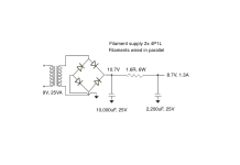
Here's my filament supply for a pair of tubes wired together and in parallel internally. It's for Rod Coleman regs V4 if anyone is still using those. V9 means you deduct 3V from the supply voltage.

Here's my filament supply for a pair of tubes wired together and in parallel internally. It's for Rod Coleman regs V4 if anyone is still using those. V9 means you deduct 3V from the supply voltage.

I made a PP amp for my Stax 'phones using the 4P1L, and used a CCS for each tube.
Wow, I would love to hear more about this. Can you share an pictures and the circuit?I made a PP amp for my Stax 'phones using the 4P1L, and used a CCS for each tube.
Cheers Grant
Limiting factors:.. but looks like 40mA is better. And at 240V a-k.
P_anode: 7.5W
P_g2: 1.5W
EF184 input with CCS @7mA (CCS being a P-FET, 2SJ74, cascoded with a 2SA1400), and 4P1L in PP using a common "ring of two" CCS comprised by a PNP transistors and a MOSFET. Zero contributed noise. One side of filament grounded. Fixed bias. 4P1L is stable for using for months before needing balance readjusment for toroidals, if is not abused in dissipation (after heating time). Will have zero issue for years for normal trafos.Wow, I would love to hear more about this. Can you share an pictures and the circuit?
Cheers Grant
During assembling stage:
Here a board having a ES9018 appears. I used for years, until I subbed it by the Valve DAC from Marcel van de Gevel.
I used only silver wire for internals. Not a ultra believer of silver wire, but I have some and wanted to use ;-)
Done:
Coupling caps being the Siemens KS series tight wound.
My wife "decouped" the PSU unit with old schematic theme.
Schematics I have it in home. I need to take a photo of it (is pencil-drawed).
PSU have Ge rectifiers for +B and for filaments.
The sound of it is outrageously transparent. Since it have low HD, less than 0.03% at almost 100V rms, corresponding to 100dB on these Stax!
Is amazing to listen something with low distortion not being high feedback; in fact, is zero feedback... is not same sound than from high feedback circuits, at least it seems for me. It maintain the spacioness of zero NFB circuits, but in any case, is not so seductive than SE circuits sounding. But the "precise" sound is something I wanted for these phones.
Mu is slightly higher due to slightly increased rp?"4P1L has a fantastic set of curves, it’s extremely linear and interestingly when filaments are connected in series and with G3 at the filament center point, the mu is slightly higher (above 9) than when in wired parallel (about 8)." Ale Moglia
https://www.bartola.co.uk/valves/2013/09/29/4p1l-model-improved/
I would prefer better linearity to increased mu.
Out of phase cross talk widens a sound stage a bit 😉It will function..... But remember that the push pull anode currents are in opposition:
- if you connect the filaments directly across each other, there will be crosstalk corruption.
This explains why they sound best with private a regulator for each DHT.
I've gone with Rod's suggestion of parallel connection. It means double the VA in the transformer but that's not really an issue.
Can I please ask you to explain this point a bit? I've never heard this comment.Out of phase cross talk widens a sound stage a bit 😉
Is it due to cancellation of small residual noise?
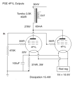
Well, I'm coming home to PSE 4P1L after a while using other outputs. I used PSE 4P1L for many years, in those days in filament bias. This time I've kept it simple and used cathode bias. The filaments are wired in parallel. It has turned out rather well into a pair of Tomiko Japanese 3.5K OPTs - by chance a good match tonally. 4p1Ls can be slightly bright and thin in the mids, and the Tomiko adds a little bit of needed warmth. I don't know what the Tomikos are gapped for but they're quite compact so I've guessed at 60mA. This gives me a dissipation of around 15.5W. I'm driving them with a 27 mesh input tube. Gain is on the limit for my system, only barely enough since the 27s are mu=9 and resistor loaded. Anyway, the sound is very clear, that nice DHT sound. So I'm pretty happy with this.


Last edited:
I have a question based on my latest build - see last post. I'm getting a weak bass response - haven't measured it but it's definitely dropping off. What could cause this and how to correct it?
Any ideas? Andy
- cathode bypass is 70uF. It's DC link so big and I can't add much more in DC Link
- only 30mA through each 4P1L. I'd like more but my OPTs are quite small, 6x6x6cm. Don't know how they are gapped
Any ideas? Andy
Try:
- Add some electrolytic cathode bypass, just to see if the bass is lifted. 220µF - 330µF will tell you if the bypass is the problem, and you can decide to fix it - or go to grid bias instead.
- What's the measured resistance of the primary? In an open-loop power amp like this, High values of R here will add to the output resistance in the speaker circuit, (by 1/N²): for 3000:8Ω divide by ~20 to refer the ohms to the secondary.
@andyjevans If you have enough gain on the driver, and the cathode bypass is enough (follow Rod's suggestion to try it before anything else) you can try connecting the cathode bypass to the secondary of the output transformer, to get negative feedback from it and improve its performance.
- What's the measured resistance of the primary? In an open-loop power amp like this, High values of R here will add to the output resistance in the speaker circuit, (by 1/N²): for 3000:8Ω divide by ~20 to refer the ohms to the secondary.
Resistance of primary is 450 ohms. Does that give any clue to what the gap might be or the mA allowed?
Tomiko SE OPTs Brand new and made in Japan 2012
10W, 15W max. 1.7K and 3.5K Primary, 0-4-8-16 Ohms secondary
265 and 405 ohm DC Resistance with 16 HenryPrimary DC current: 165ma Max.
Frequency range: 10Hz ~ 55 Khz(-3dB) / 10Hz ~ 78Khz(-1dB at 1 watt)
So i managed to get more information. It looks like I can put 70mA through them.
I found another data.I'm getting a weak bass response - haven't measured it but it's definitely dropping off.
This Tomiko OPT has only 21H primary inductance, which have 2639 Ohm impedance at 20Hz.
For 3k5 the required Lp is 28H.
The high primary DCR (430R)also causes more loss.
p.s.
If you raise the cathode blocking capacitor value, the -3dB goes down, but around 20Hz the unpleasant hump growing.
p.s.2
Some simulation 21H/430R primary, 278V/30.7mA op.point.

Last edited:
- Home
- Amplifiers
- Tubes / Valves
- One more 4P1L SE