Thank you so much for the info!
Is the 50v line to AM2 also needed for the test to work?
If it's not too much trouble, from a very high level perspective, can you tell me what the 15v and 55volts do in AM1 with this circuit?
Thanks Again.
Is the 50v line to AM2 also needed for the test to work?
If it's not too much trouble, from a very high level perspective, can you tell me what the 15v and 55volts do in AM1 with this circuit?
Thanks Again.
Last edited:

Well Q39 and 40 test good, so I will proceed to add the -50/+50 and the -75/+75 to that board and see if I can pass a signal to the output. So that board should get me the 55 volts and also the 15 volts I need.
I should be replacing some other old caps on that board but only if I get a signal through both channels. Let you know.
I should be replacing some other old caps on that board but only if I get a signal through both channels. Let you know.
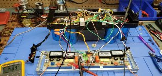
Well success!! Both AM1 and AM2 are good on my board. I have posted a crude setup but this gives me the 15 and 55 off the original supply.So I will continue then and order some TO-3 PNP for the O/P module. Just going back, I bought it from a fellow which he says it sat for over 10 years on a shelf. It was looked at by a tech and started to replace outputs on CH2. So far I have verified PS is good and the driver modules works. Anyone had good results with the transistors from Mouser by ONSEMI, I think, have to look at the Bom I have saved there.
Attachments
Update, replacing the 1 NPN predriver on the right channel and 2 PNP TO-3 , the amp is now working on both channels.
The right channel has about 20 mv DC offset but the left channel which was not touched has -7 volts DC off set, this is with the meter leads, red on pos, neg on black. It sounds ok, runs warm , it ran the other day for 2 hours. Anyone know a quick way to narrow down where the -7 offset is coming from? I did check all the NPN and PNP on the left channel, none were open or shorted. I have never worked on anything that did have an offset adjustment. Any help would be appreciated if you have run into this before.
The right channel has about 20 mv DC offset but the left channel which was not touched has -7 volts DC off set, this is with the meter leads, red on pos, neg on black. It sounds ok, runs warm , it ran the other day for 2 hours. Anyone know a quick way to narrow down where the -7 offset is coming from? I did check all the NPN and PNP on the left channel, none were open or shorted. I have never worked on anything that did have an offset adjustment. Any help would be appreciated if you have run into this before.
Offset is coming from the modules.
Either the resistor array drifted or the transistors. Also check Q33-36
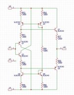
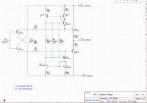
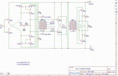
Comparison between the old schematic vs the new on the AM-2
Either the resistor array drifted or the transistors. Also check Q33-36
Comparison between the old schematic vs the new on the AM-2
Attachments
Last edited:
So you think the neg DC on the left channel is coming from the AM-1, AM-2 modules? I thought maybe it might be one of the outputs TO-3 transistors on the neg bank causing this. I can't hear it through the amp, but my meter can measure it. I will double check by putting a 1khz signal through, referencing the scope to the centre, and if there is neg DC offset, it should pull the sine wave towards the bottom by 7 volts. Also if I was to disconnect the input of the AM-2 going into the power modules, then the offset if it is being caused my these predriver modules should disappear correct?
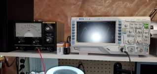
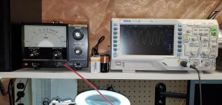
Ok, I rechecked and it's actually closer to -9v DC offset on left channel. I verified this by using the sine wave and you can see the output is lower on the scope when referenced at the centre of the screen, the right channel with no offset stays in the centre.
I disconnected the output from AM-2 going to the 200ohm(R39) on the power section of the left channel and the DC offset is still there. So it seems like it's in the power section of the left channel. Am I correct to assume this? Not sure what else in that predriver board would have anything to do with making the neg DC offset.
I disconnected the output from AM-2 going to the 200ohm(R39) on the power section of the left channel and the DC offset is still there. So it seems like it's in the power section of the left channel. Am I correct to assume this? Not sure what else in that predriver board would have anything to do with making the neg DC offset.
Did you ground the input?
Check Q1,2,7,8
The AM-5 was used in pre-amps and i believe one of the larger amps.
Check Q1,2,7,8
The AM-5 was used in pre-amps and i believe one of the larger amps.
Last edited:
No, I did not ground the input to measure the DC offset. So that would be Q7/Q8 on Ch1(Left) which gets power from -50v. You thinking it's possibly the 2 NPN's causing the neg offset? Pain in the butt to tear it apart again and remove those circuit boards...I do have 2 NPN's . It can't be anything on those circuit boards which mount above the TO-3, as I rebuilt them all. I measured them all, but possibly under load they are causing issues.
Well replaced Q7 and Q8 , and now with only 50VAC coming off the variac I still have -9V on the left channel speaker terminals. Scared to turn it up any further. I think this is boat anchor now....too hard to work on to take apart
Still think it’s the modules, you can’t isolate the circuit in the methods you are using. The amplifier won’t behave properly and needs the entire circuit intact
Appreciate all your help, that would be making up 4 module boards..can't make 2 for the left channel and leave the right 2 stock. I have to think how much more I am willing to sink into this boat anchor. Have you got the files to get the boards made up and a parts list for all the modules. I want to assess everything before I carry on, or just take a loss and sell the unit as is and someone can use it for parts or repair it.Again, thanks for all your help and suggestions....
You probably should of replaced the boards to begin with.
These are not robust and almost always fail.
These are not robust and almost always fail.
Ya, probably should have, but I did have gain through both modules so I decided to continue and fix right channel. It ran fine, but then noticed high neg offset in left channel. Not sure what to do with it, probably put it on the shelf till I decide. Even bought 4 new 100uf/100v caps for PS.
I'm repairing a D-110 with faulty modules on both sides. This thread about the AM-1 and AM-2 modules is great. There is an important addition! Beware: the modules on the left side are a mirror compared to the right side. So you need 4 boards, all different. Back to the drawing board.
Well with full power AC in the right channel is showing +50v across speaker terminals and left channel -50v across speaker terminals. Before I changed out the 2 NPN TO-3 in the left channel( neg) bank, the right channel only has less than 20mv of offset. I'm stumped now. I normally work on tube amps and don't have tons of expertese on SS amps. Not sure what I did when I changed out those transistors. I think this is going to be sold as is....unless I can find someone with lots of knowledge to help work through this. Thanks to deafbyhorns who has offered some suggestions. Might be a good parts unit for someone.
The setup of the D110 is not very different from other AB class amps. In general: when there is DC on the output is equal to the powersupply voltage the drivers or a power transistor is broken. When there is another voltage on the output like a couple of volts mostly the first VAS is broken. That is the input cirtcuit around the first 2 transistors at the input. They fail often. When the DC on the output is not stable it could be the LM358. This is a DC offset circuit. Hope it helps toubleshooting. Replacing the annoying modules is the only way to go in these amps.
- Home
- Amplifiers
- Solid State
- How to fix the Audio Research D-110 modules