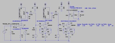
That would work fine. Why are C11 and C13 marked as 10uF? Surely 0.1uF is enough, and I'd use FT-3 teflons? Big step up in sound quality. The 6B4G tubes only need 470K grid leaks. Be sure to put 30mA or more through the 4p1L, in fact 40mA is the sweet spot and 240V a-k. See the 4P1L SE thread.
Ref. to my post above. A real budget solution could be if using Tubelab style heating. Question is if it would work, with the same heater supply for both 2nd and 3rd tube.

Thanks for pointing this out. 10u is what I use when simming. As the amp will be used from 200Hz and up, the caps will be even smaller than the ones you suggest.Why are C11 and C13 marked as 10uF?
About the 4P1L I used the figures Ale suggested in one of his preamp sketches. Both CCS are 30mA. As I only have a 300V anode supply, I guess I could rise the input Ua to at leas 200V. About grid leaks it seems like 50k or 100k is suggested for fixed bias and 470k for cathode bias. Wrong voltage on the 6B4G regulators, should be about 9V raw.
Last edited:
That would ruin me, will go for regulators for the 4P1L to begin with ;-).Ah - you are using fixed bias for the 6B4Gs? I didn't notice that at a quick glance. I'm a big fan of Rod Coleman's regs - his V9 is very nice indeed. You would need 6 of them in this case.
Hi Bela, checked both and connecting to the upper side of source resistor actually worsened the performance. With both triodes having Ra of close to 1k it will probably work real good anyway. The signal will not go through the MOSFEts which seems to give the circuit a higher H3 content compared to H2?The setting resistor (in this case 40R) lower leg has high impedance, the other side is much lower.
Would really appreciate if you tried a few sims.
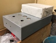
It would probably be wise to leave room for extra regulators plus heatsinks in the chassis, once you get a taste for them you'll stop looking for other solutions.That would ruin me, will go for regulators for the 4P1L to begin with ;-).
Hi Lars,Hi Bela, checked both and connecting to the upper side of source resistor actually worsened the performance.
If you use cascode CCS loaded VAS stages at proper tube operating points, the distortion can be kept under control with even very low level.
sample:
cCCS loaded 841->cCCS loaded 10Y CF driver breadboarded, 60V RMS (170Vpp) output (0.019% THD).

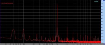
The simulation's FFT just so accurate as mathematical model of components, the order of magnitude shows approximate value of real measurement.
The harmonics -and its distribution- depends more the model, the first few pieces are still generally reliable, the others IMO aren't (usually these are very small, the overall THD depends on the first three or four components).
The simulation usually shows close to real operation, but it does not replace human expertise.
For example the simulated 6B4G SE stage shows good working at 300V 60mA circumstances, while the ideal operating point must be at lower voltage.
I simulated similar layout, that your schematic, with more focusing to datasheet curves.

Hi Bela, please send me the *.asc to let me evaluate your circuit, as I have also focused on datasheet curves for 6B4G(Audiomatica 2A3). I am with you on a little higher Ua but not about Ia. It will be fun to compare and adjust both models, before I begin building. I will not have more than ca 280V B+ available,I simulated similar layout, that your schematic, with more focusing to datasheet curves.
Running the 6B4G output valve at 290V/52mA/3.5k is in my view better wrt H3.
- Home
- Amplifiers
- Tubes / Valves
- All-DHT amplifiers: no indirectly heated signal tubes!
