I have a recently acquired Kenwood KD-770D with a speed problem. It appears that the PLL is not working because the table runs about 54 RPM at both 33 and 45 settings. PLL lock LED doesn't engage. I'd appreciate any suggestions on troubleshooting this table, thanks.
EDIT: I'm just looking for suggestions based on prior experience with this table (or similar, e.g. KD-990). Just trying to shortcut the solution with information from someone who's already been there. Cheers.
EDIT: I'm just looking for suggestions based on prior experience with this table (or similar, e.g. KD-990). Just trying to shortcut the solution with information from someone who's already been there. Cheers.
Last edited:
I would start with the basics, look at the FG signal on IC3 pin 7 ? And also the signal on IC1 pin 12 ? Maybe the refrance is on IC1 pin 14/15 ?
Do you know what IC5 and IC1 are ? Datasheet ?
Others may help too ??
Do you know what IC5 and IC1 are ? Datasheet ?
Others may help too ??
Last edited:
Thanks for the suggestions. That will be a good starting point when I get back home.
IC1 = TC9142P
IC5 = UPD7520C-028
IC1 = TC9142P
IC5 = UPD7520C-028
The fact that it is running fast is your first clue. If it was running slow, that would indicate the reference signal (divided down xtal) is missing because no matter how slow the FG signal was, it would still be higher than the reference (zero) and the output would be trying to further slow the platter. The opposite is true in this case: No matter how fast the platter is turning, if the FG signal is missing (zero) the loop will try to increase the speed to bring it up to the reference.
As Dave said, look at IC3 pin 7; chances are there is no signal there. If there is a signal, look at IC1 pin 8 (AFC output) and IC1 pin 13 (Strobe output). If there is a signal at pin 13, the reference signal should be OK. If pin 8 is at Vcc, then something is getting lost inside of IC1 from pin 6 (FG input) to the phase comparator or loop output.
As Dave said, look at IC3 pin 7; chances are there is no signal there. If there is a signal, look at IC1 pin 8 (AFC output) and IC1 pin 13 (Strobe output). If there is a signal at pin 13, the reference signal should be OK. If pin 8 is at Vcc, then something is getting lost inside of IC1 from pin 6 (FG input) to the phase comparator or loop output.
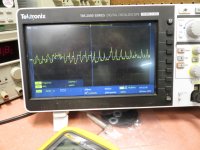
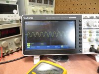
OK, here's what I found. There is a signal at pin 7 of IC 3, but it's odd looking:

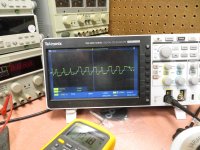
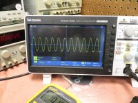
It's not stable but frequency is approximately 33 hz. The service manual doesn't give any idea of the expected output at pin 7 but it does show the expected signal at pin 1 of IC3. It should be approximately square wave at 20Hx for 33 rpm and 27Hz for 45 rpm. Here's picture. Doesn't' match the chape. If I slow the platter with my finger to 33 rpm, I get about 20Hz in this waveform:

So it appears to me that the frequency generator from the motor is working - at least generally.
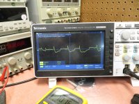
Here's the signal at pin 8 of IC1

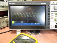
And here's a picture of pin 13 at IC1

It's not stable but frequency is approximately 33 hz. The service manual doesn't give any idea of the expected output at pin 7 but it does show the expected signal at pin 1 of IC3. It should be approximately square wave at 20Hx for 33 rpm and 27Hz for 45 rpm. Here's picture. Doesn't' match the chape. If I slow the platter with my finger to 33 rpm, I get about 20Hz in this waveform:
So it appears to me that the frequency generator from the motor is working - at least generally.
Here's the signal at pin 8 of IC1
And here's a picture of pin 13 at IC1
So now I'm wondering if it's the motor control IC - IC2. It's difficult to get access to this IC in circuit but I think that's my next move.
I'd be looking at the input amp (IC3). The signal at pin 1 should be ~7.4VPP but according to your scope, it is only 339mV. Look at the DC voltages from the schematic to see where the problem is. The first half of IC3 should have very high gain. The second half is a comparator with hysteresis (schmidt trigger) biased at Vcc/2. The input to the 2nd stage is DC coupled from the first and from your scope display, some of the pulses are missing meaning the DC voltage on IC3 pin 6 is too far from Vcc/2. You should see the same frequency at IC3-7 as IC3-1; IC3-7 should be close to 50% duty cylce square waves.
I have some thoughts but will wait for the above first.
BTW any chance of the complete service manual ?
BTW any chance of the complete service manual ?
Thaks Dave. I will post complete manual when I get back home later today. I'll also do the investigation suggested by Pyramid.
Last edited:
First let me thank you guys for hanging in there with me. It's frustrating but I'm learning a lot.
The full service manual is attached. The quality is a bit sketchy but mostly usable.
I spent several hours looking at the table. I think I've measured all the voltages on the schematic and looked at all the waveforms in the service manual. Most were normal.
The biggest discrepancy was the voltage across R24. Supposed to be 120mV but actually about 2 mV. R24 and R23 are paralleled and connected to pin 20 of IC2, motor driver. Unfortunately I can't find a data sheet for this IC (Toshiba TA7234P) so I don't know what pin 20 is. These are fed from Q2. Schematic says voltage at the emitter of Q2 should be 23.4v but actual measurement is 26.4. I don't see any other spots that would cause this voltage to be high (but that may just be my misunderstanding).
All the voltage supplies to the ICs are correct.
VIN1 (pin 16 of IC2) should be 5.1V with quartz lock but it's 7.1V (of course it's not locked)
VIN2 (IC 2 pin 18) is fine
voltage at the base of Q3 should be 3.1V if locked, but it's 5.75
I looked at all the waveforms and they were similar but not exactly like shown on the schematic, except for the one across R24, as mentioned already.
I have photos and will post them next.
I did find a bit of something that appeared to be metallic across pins 24 and 25 if IC 5. I removed it and no change. Pin 24 apears to be unconnected from schematic so I doubt it made a difference.
Attachments
Last edited:
Pin 8 IC3 is 8.7V (OK) Pin 3 IC3 is 3.9v (OK per schematic) Pin 6 IC3 is also 3.9DCV (not specified on schematic but just under half of Vcc).I'd be looking at the input amp (IC3). The signal at pin 1 should be ~7.4VPP but according to your scope, it is only 339mV. Look at the DC voltages from the schematic to see where the problem is. The first half of IC3 should have very high gain. The second half is a comparator with hysteresis (schmidt trigger) biased at Vcc/2. The input to the 2nd stage is DC coupled from the first and from your scope display, some of the pulses are missing meaning the DC voltage on IC3 pin 6 is too far from Vcc/2. You should see the same frequency at IC3-7 as IC3-1; IC3-7 should be close to 50% duty cylce square waves.
All the DC measurements quoted above were made with the platter stopped. The waveforms were taken with the platter running.
I just measured the voltage across R24 with platter running. It's about 160mV - so a bit high.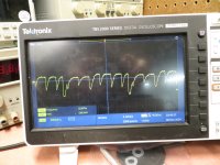
I'm guessing this isn't out of range.
So this seems to point back to the FG amp. I'm wondering if I shouldn't just replace the IC3 and give it a try. IC3 is currently AN6562, which appears to be a conventional opamp (Panasonic). I'm wondering if NE5532 would work.
I just measured the voltage across R24 with platter running. It's about 160mV - so a bit high.

I'm guessing this isn't out of range.
So this seems to point back to the FG amp. I'm wondering if I shouldn't just replace the IC3 and give it a try. IC3 is currently AN6562, which appears to be a conventional opamp (Panasonic). I'm wondering if NE5532 would work.
Last edited:
- Home
- Source & Line
- Analogue Source
- PLL not working on Kenwood KD-770D - Suggestions Appreciated
