im unsure if the resistor is really nessecary, just added it to elimate any kind of "illegal load"I'm curious about the purpose of the 1 kΩ in series with the input. If you're going for ESD protection, I suggest a pair of diodes to V+ and V- instead. If not, you can go without the 1 kΩ.
you are probably referring to zener diodes towards GND on each input, right?
i read the input voltage shouldnt exceed the power supply voltage, so for a 12V design i could just use some around 10V zeners?
i figured since XLR can usually reach up to 6V, its probably best to have a bit of headroom, 9-11V zener plus 12V power supply seems like a good combination, also in regards to using different opamps
about the feedback resistor, i wasnt sure if i even can add one, since tutorials suggests for unity gain you need a direct connection between output and inverting inputThe 10 Ω can be handy for driving longer cables. Some put it inside the feedback loop.
thanks for the suggesting, i probably go for it 🙂You'll probably want 100 nF for the local bypassing. I'd use X7R ceramic rated for at least 50 V. They'll have lower ESR and higher SRF than the Wimas.
You'll want 10-47 uF on each rail where the power enters the circuit board. I'd use a plain electrolytic cap for this. There's no reason to go overboard here. More is not always better.
as i was choosing resistors for the opamp buffer i saw
Yageo MFR resistors, 50ppm/1% metal film resistors with electrolytic copper leads, this cant be too far off from "audiophile pure copper leads" like on the takman resistors right?
i might actually change from kiwame 2w footprints to 0,5W footprints and order 2 boards preassembled and some boards without resistors where i will check out takman resistors on and compare...
would you say, on these general purpose resistors, that i should go for yageo MFR, or can you recommend others that are available at LCSC.com?
No, the standard protection pn-diodes to V+ and V- to stop the input straying outside the range V- to V+ by more than 0.6V or so. The zener "solution" doesn't work when the circuit is powered down, for instance.you are probably referring to zener diodes towards GND on each input, right?
Normally ESD protection consists of series resistance, then the diodes to the rails, and sometimes another resistor afterwards.
ah.. probably like this then:
https://www.mpdigest.com/wp-content/uploads/2016/02/Figure_01-1-1024x819.jpg
they used schottky diodes, for only 0.4V

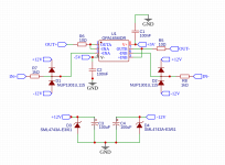
D3 and D4 are 13V 1W zener diodes
D1 and D2 are Nexprexia esd protection IC's including two diodes
C1 and C2 are Yageo 100nF 50V X7R ceramic caps
C3 and C4 are Panasonic Electrolytic caps, 61mohm ESR
Two Questions:
https://www.mpdigest.com/wp-content/uploads/2016/02/Figure_01-1-1024x819.jpg
they used schottky diodes, for only 0.4V
D3 and D4 are 13V 1W zener diodes
D1 and D2 are Nexprexia esd protection IC's including two diodes
C1 and C2 are Yageo 100nF 50V X7R ceramic caps
C3 and C4 are Panasonic Electrolytic caps, 61mohm ESR
Two Questions:
- is 10 Ohm R3 and R4 for the output sufficient or should i increase this a bit? i read it can prevent oscillation
- can i safely remove R1 and R2 input resistors? what kind of current can i expect on unbalanced/balanced audio signals?
Attachments
This would be one way to include the 10 Ω inside the feedback loop and still have unity gain.

But you will need to run a stability analysis if you have the resistor inside the feedback loop. Or at least I'd encourage you to do so. If you go with the circuit you posted you won't have stability issues, but you will have 10 Ω output impedance.
The ESD protection diodes do not need to be Schottky, but it (probably) doesn't hurt if they are. I say "probably" because I don't know how reverse biased Schottky diodes will impact things like distortion. They probably won't impact much, but the OPA1656 has very low distortion. It'd be a shame to wreck that with the ESD protection.
What's the idea with the two 13 V zener diodes? Over-voltage protection? With the circuit as-is any power supply worth its salt will just blow the zeners. Also keep in mind that zener diodes are not precision devices, so you'd probably want 15 V zener diodes if your goal is to protect the circuit ... and add some series resistance so they don't fry immediately if someone attaches too high a voltage.
Tom
Some use 0 Ω. Some use 47 Ω. Anywhere in between is probably good. It's highly non-critical.
- is 10 Ohm R3 and R4 for the output sufficient or should i increase this a bit? i read it can prevent oscillation
I'll answer this in the form of a homework question for you: What's the input impedance of the non-inverting input of an opamp? The input current would then be Vin/Zin.
- can i safely remove R1 and R2 input resistors? what kind of current can i expect on unbalanced/balanced audio signals?
Tom
There are very low capacitance Schottky diodes that can be used for input protection at lower voltages. One I have used is: MA4E1339A1-287T
the idea came from this: https://sound-au.com/articles/esd-protection.htm which suggests the zener is required for the ESD protection to actually work (?)What's the idea with the two 13 V zener diodes? Over-voltage protection? With the circuit as-is any power supply worth its salt will just blow the zeners. Also keep in mind that zener diodes are not precision devices, so you'd probably want 15 V zener diodes if your goal is to protect the circuit ... and add some series resistance so they don't fry immediately if someone attaches too high a voltage.
alright, maybe i will play around with this later on, for now 10 ohm seems good thenSome use 0 Ω. Some use 47 Ω. Anywhere in between is probably good. It's highly non-critical.
I'll answer this in the form of a homework question for you: What's the input impedance of the non-inverting input of an opamp? The input current would then be Vin/Zin.
actually unsure which one i would take here, but i will just go with the lower one of 100 MegaOhm
So.. 12V / 100.000 ohm = 0,00012A, which is 0.12mA ? 0.06mA for 6V inputs
So no need to worry with high impedance inputs like this i guess
Tho i found this discussion:
https://electronics.stackexchange.c...r-in-the-feedback-path-of-a-unity-gain-buffer
which suggest using a input resistor equal to the feedback resistor to match impedances, so i could add a 10ohm resistor just for good measure?
just let me get this straight, adding a feedback resistor in an unity gain buffer will actually increase noise, because less feedback is provided, but some say less feedback sounds "better" because it doesnt get adjusted as hard/precisely, right?
i think i will adjust your circuit, using a seperate feedback resistor, but populating all 3 spots (output, input, feedback) with 10 Ohm for now, so i can actually experiment with feedback/input resistors later on
Thanks for the help 🙂
Try to think it through.the idea came from this: https://sound-au.com/articles/esd-protection.htm which suggests the zener is required for the ESD protection to actually work (?)
If the ESD strike is positive, the diode from the input to V+ conducts. The energy goes into the power supply. Let's say you have 10 uF there and you have a 20 kV ESD strike. Assuming human body model (100 pF + inductance), you're looking at 20k * 100p/10u = 0.2 V buildup on the power supply. Hardly anything to worry about.
If the ESD strike is negative, the diode from the input to V- conducts and you get an additional -0.2 V on the power supply.
Rod is right. To fully protect the IC you also need a zener clamp (or similar) from V+ to V-, but you will likely find that plain zener diodes have too high internal resistance to properly protect the IC. Also, Rod neglects that the IC has its own internal protection both on the inputs and across the power supply. The internal protection is intended to protect the IC during circuit assembly (under ESD controlled conditions), not to protect the IC against anything the end user of some equipment might throw at it.
Actually, 100 MΩ = 100,000,000 Ω, so you're looking at 12/100E6 = 120 nA.So.. 12V / 100.000 ohm = 0,00012A, which is 0.12mA ? 0.06mA for 6V inputs
So no need to worry with high impedance inputs like this i guess
Tom

thanks, i will remove the zeners, following your calculations with 100uF caps its only 0.02V ...
coming up with stuff with my limited knowledge is fairly hard sometimes, i barely do electronic stuff beside some audio projects...
then coming up "with the best way" is a rabbit hole in its own...
learned so far quite a bit about impedances

So this should be the final circuit.. i hope the seperate feedback & output resistor works out, else correct me please 🙂
One new question i have
if you look into audiotransformers you usually find 10k:10k or 600:600 impedances, i already figured i probably want 10k:10k, the question is should i worry about the 10k input impedance + 10k input impedance of the relay attenuator? since its a fairly close to eachother...
or is this actually a use case for a 10k:600 ohm transformer?
hooking the transformers between input boards and relay attenuator also comes with the benefit of using the same two transformers for multiple inputs.... if you wanna go out RCA you just grab the positive signal
i guess it would be also possible to reuse 2 outputs for both.. XLR and RCA
Question is, what transformers you would recommend? i heared jensen quite a bit but hard to come by in germany as it seems
i found this one https://www.aliexpress.us/item/3256806682969257.html
audiophonics also has some positive reviews, probably good enough to start off with?
ah should have looked it up i was actually unsure with the conversion... thanks for correctingActually, 100 MΩ = 100,000,000 Ω
coming up with stuff with my limited knowledge is fairly hard sometimes, i barely do electronic stuff beside some audio projects...
then coming up "with the best way" is a rabbit hole in its own...
learned so far quite a bit about impedances
So this should be the final circuit.. i hope the seperate feedback & output resistor works out, else correct me please 🙂
One new question i have
if you look into audiotransformers you usually find 10k:10k or 600:600 impedances, i already figured i probably want 10k:10k, the question is should i worry about the 10k input impedance + 10k input impedance of the relay attenuator? since its a fairly close to eachother...
or is this actually a use case for a 10k:600 ohm transformer?
hooking the transformers between input boards and relay attenuator also comes with the benefit of using the same two transformers for multiple inputs.... if you wanna go out RCA you just grab the positive signal
i guess it would be also possible to reuse 2 outputs for both.. XLR and RCA
Question is, what transformers you would recommend? i heared jensen quite a bit but hard to come by in germany as it seems
i found this one https://www.aliexpress.us/item/3256806682969257.html
audiophonics also has some positive reviews, probably good enough to start off with?
What are you looking to accomplish with R5 and R6?
Also, U1B has positive feedback. Are you looking to build an oscillator? If so, you need a capacitor there too to set the frequency. 😉
Sergio Franco, Design with Operational Amplifiers and Analog Integrated Circuits is a worthwhile read if you're looking to gain more knowledge about how to use opamps. It's kinda expensive, but the older editions may be available for less. There's not a lot of difference between editions from the 2nd and up. I was told at one point that you can find it as a free .pdf download; probably not with the author's or publisher's approval.
Tom
Nono, i just wasnt able to find a balanced schematic, so i kinda assumed minus voltage needs to go to minus input, both inputs go now to the plus input and feedback to minusAlso, U1B has positive feedback. Are you looking to build an oscillator? If so, you need a capacitor there too to set the frequency. 😉
just so im able to change and match feedback resistors + input resistors, without nessecarly changing output impedanceWhat are you looking to accomplish with R5 and R6?
more variables to play with later on, tho im unsure if this does introduce gain with two resistors on the output/feedback
EDIT: oh i probably got it, your schematic connects the "output" directly to feedback after the output resistor, so feedback still gets 1:1 what the opamp throws out, my schematic probably messes with gain...
maybe it works out with two resistors with the same value, but if i need to swap them both i can also just use your schematic i guess 🙂
Last edited:
A balanced schematic?Nono, i just wasnt able to find a balanced schematic
Are you taking input from a balanced source, i.e., one with XLR output? Or is the input to this circuit coming from your attenuator? Where does this buffer fit in the grand scheme of things?
Tom
Are you taking input from a balanced source, i.e., one with XLR output? Or is the input to this circuit coming from your attenuator? Where does this buffer fit in the grand scheme of things?
Tom
the op amp buffer should sit behind the relay attenuator, everything going trough the attenuator is actually balanced, i will use audio transformers for the rca inputs BEFORE the relay attenuator , so everything entering the attenuator board is balanced, for rca outputs i only use the positive signal
not sure if this is the best way todo, but it has some advantages
- rca input to xlr output is possible (transformer balancing every rca input)
- xlr input to rca output is possible (just hooking up the positive signal) (now thinking about it, i actually need to adjust the level... 6V XLR vs 2V RCA)
- only one pair of transformers for 2/4/6/8 rca inputs
Did i miss something or why you are asking?
I don't understand what you mean by "behind". Is this what you have in mind?
RCA/XLR input -> Transformer -> Balanced Attenuator -> Balanced Buffer -> Balanced Output
If so, you don't need the ESD protection on the input to the buffer. Instead just use common-sense ESD precautions when you assemble the preamp. Instead I would move the ESD protection to the output of the buffer. Use a pair of beefy diodes like 1N4007 from OUT to V+ and V-.
Tom
yepRCA/XLR input -> Transformer -> Balanced Attenuator -> Balanced Buffer -> Balanced Output
these should be all possible routes:
RCA -> Transformer -> Balanced Attenuator -> Balanced Buffer -> XLR
RCA -> Transformer -> Balanced Attenuator -> Balanced Buffer -> RCA, only using positive signal
XLR -> Balanced Attenuator -> Balanced Buffer -> RCA, only using positive signal
XLR -> Balanced Attenuator -> Balanced Buffer -> XLR
you probably say this because there is a transformer right? i want to wire the transformer so its preferably only used on RCA inputs (i might need to add a relay to disconnect the transformer tho)If so, you don't need the ESD protection on the input to the buffer. Instead just use common-sense ESD precautions when you assemble the preamp. Instead I would move the ESD protection to the output of the buffer. Use a pair of beefy diodes like 1N4007 from OUT to V+ and V-.
Or do you have another idea to implement interchangeable rca and xlr inputs/outputs in another way? atleast this was the easiest way i could think of
No. I'm saying this because when you assemble the preamp you have control over the electrostatic buildup. You can take measures such as working on an ESD safe surface, grounding yourself, etc. So you don't need ESD protection between the attenuator and the buffer. The end user will never be able to touch it.you probably say this because there is a transformer right?
I would have ESD protection at the preamp inputs (so before the transformer) and outputs. If the only active element is the OPA1656 buffer then I suppose you can put the ESD protection there. The only time it'd activate is if an ESD strike made it through the transformer while the attenuator was set to 0 dB.
The input is the easy part. You can use a DPDT switch to switch RCA centre, RCA shell and XLR pins 2,3. Connect RCA shell to XLR pin 1.Or do you have another idea to implement interchangeable rca and xlr inputs/outputs in another way?
The output is more of a challenge. The best solution would be to use a differential amp to convert from balanced to single-ended for the RCA output.
Tom
grounding i do anway when handling PCBs (building a PC and such), just bought a reserve grounding wristband recently, so im not too worried about ESD while assemblingNo. I'm saying this because when you assemble the preamp you have control over the electrostatic buildup. You can take measures such as working on an ESD safe surface, grounding yourself, etc. So you don't need ESD protection between the attenuator and the buffer. The end user will never be able to touch it.
since the inputs are passive i would need to get the voltage rails there, it might be easier to just leave it on the OPA1656 buffer, since its the only part that actually can get damaged by ESD, right?I would have ESD protection at the preamp inputs (so before the transformer) and outputs. If the only active element is the OPA1656 buffer then I suppose you can put the ESD protection there. The only time it'd activate is if an ESD strike made it through the transformer while the attenuator was set to 0 dB.
i did a bit of reading since yesterday and this topology doesnt seem uncommon either:The input is the easy part. You can use a DPDT switch to switch RCA centre, RCA shell and XLR pins 2,3. Connect RCA shell to XLR pin 1.
The output is more of a challenge. The best solution would be to use a differential amp to convert from balanced to single-ended for the RCA output.
Balanced in -> conversion to single ended -> single ended internals -> conversion to balanced -> balanced out
im actually wondering what effect it would have on noise rejection having the internals balanced straight trough vs "termination" (where basicly noise rejection takes place/starts) on inputs/outputs
You know the schematic better than I do.since the inputs are passive i would need to get the voltage rails there, it might be easier to just leave it on the OPA1656 buffer, since its the only part that actually can get damaged by ESD, right?
That's what I did in my DIFF PRE. I used THAT1200 to convert from differential to single-ended, ran single-ended internally, and converted back to differential with a THAT1246.Balanced in -> conversion to single ended -> single ended internals -> conversion to balanced -> balanced out
The THAT12xx are somewhat noisy, so I wouldn't use them today, but there's nothing wrong with the topology.
You have full control of everything that happens within the preamp chassis so you can design it such that you don't corrupt the signal with noise.im actually wondering what effect it would have on noise rejection having the internals balanced straight trough vs "termination" (where basicly noise rejection takes place/starts) on inputs/outputs
Tom
hmmm i found this one https://diy.thcustom.com/?wpdmdl=3207
suggesting the THAT1646 as DRV134 replacement, do you have expierence with this one?
something like this could be an "all in one board"

you can switch between
1. passive passtrough
2. using only THAT1646 for balancing a unbalanced signal
3. using only the buffer for balanced
4. using that1646 + buffer for a unbalanced signal
atleast this is the best idea i came up with
im just not sure if the 2. option is really necessary, since there already is a is active balancing circuit, i can probably buffer it all the time
suggesting the THAT1646 as DRV134 replacement, do you have expierence with this one?
something like this could be an "all in one board"
you can switch between
1. passive passtrough
2. using only THAT1646 for balancing a unbalanced signal
3. using only the buffer for balanced
4. using that1646 + buffer for a unbalanced signal
atleast this is the best idea i came up with
im just not sure if the 2. option is really necessary, since there already is a is active balancing circuit, i can probably buffer it all the time
- Home
- Source & Line
- Analog Line Level
- DIY Volume Control (Relay Attenuator)