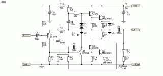
No constant current sources (except bootstrap) no vbe multipliers no current mirrrors and no zener diodes.
The circuit is a simplified version of the "audioamp" example circuit in ltspice.
I could probably remove one transistor but the amount of passive components such us trimpots and capacitors would increase significantly,
i should also add an input capacitor and an volume control potentiometer to this circuit.
The reason i chose 2n3055's is becuse i found an literal bag of them (and tesla kd205/203).
Have a good day night or whenever you are reading this post, feel free to leave feedback and suggestions on how to improve this circuit while keeping its simple nature.
Attachments
R2 value looks very low. DC offset on output might be very high.
Why such high value for R4?
With no current mirror in simple circuits you have to balance the differential currents.
Q1 is loaded by Q3. Review the currents in your model or do DC analysis on the output.
Adjust R2 for lowest DC on the output which tells your differential is balanced.
VR1 as a current source can work, just not very well unless the rails are regulated.
Vary your voltage rail by a few volts say 11 to 10 volts and you will see that DC
offset on the output will dance like crazy in the real world. Easier to use simple current source.
BD139/40 be better drivers.
3904/06 get pretty hot driving a power transistor
Even though simplified amplifier
better to use baxadall diode for CFP pair.
Negative rail will reach clipping earlier and most the AC current will be
going to only one 2N3055
For single supply R16 and R18 wouldnt work well in real life.
You have to stabilize the DC. Usually just 2 resistors with a capacitor
to stabilize the DC
Dual Rail model has no DC coupling. This is just asking for trouble.
Specially with a simplified model that already has high DC offset.
When combining Emitter follower and CFP for Quasi output.
Very important DC is stable. Again with no Diode in CFP
and DC offset. Almost All the AC current will go to one or the other output transistors.
Last edited:
meaning i do have to use a bunch of weird circuits that dont make any sense to me to make something usable, and confuse myself to death when assembling them on a perfboard or wait for an pcb to arrive. i think i should stay with se amplifiers and just use a big hunk of metal as a heatsink.
maybe just copy the audio innovations alto? or make jlh1969 work in class ab?R2 value looks very low. DC offset on output might be very high.
Why such high value for R4?
With no current mirror in simple circuits you have to balance the differential currents.
Q1 is loaded by Q3. Review the currents in your model or do DC analysis on the output.
Adjust R2 for lowest DC on the output which tells your differential is balanced.
VR1 as a current source can work, just not very well unless the rails are regulated.
Vary your voltage rail by a few volts say 11 to 10 volts and you will see that DC
offset on the output will dance like crazy in the real world. Easier to use simple current source.
BD139/40 be better drivers.
3904/06 get pretty hot driving a power transistor
Even though simplified amplifier
better to use baxadall diode for CFP pair.
Negative rail will reach clipping earlier and most the AC current will be
going to only one 2N3055
For single supply R16 and R18 wouldnt work well in real life.
You have to stabilize the DC. Usually just 2 resistors with a capacitor
to stabilize the DC
Dual Rail model has no DC coupling. This is just asking for trouble.
Specially with a simplified model that already has high DC offset.
When combining Emitter follower and CFP for Quasi output.
Very important DC is stable. Again with no Diode in CFP
and DC offset. Almost All the AC current will go to one or the other output transistors.
If you want to understand more about why things like current mirrors and current sources greatly improve amp performance, This paper by Doug Self is a possible starting point: http://douglas-self.com/ampins/dipa/dipa.htm
Another simple improvement you can make is reduce the Johnson noise in the input and feedback networks by scaling down the resistor values. For instance scaling R1, R6 and R7 down by a factor 10 will reduce noise (hiss). C3 will have to scale up to match though. This is usually only worth doing with if you can here hiss in the tweeters with shorted amplifier input.
Another simple improvement you can make is reduce the Johnson noise in the input and feedback networks by scaling down the resistor values. For instance scaling R1, R6 and R7 down by a factor 10 will reduce noise (hiss). C3 will have to scale up to match though. This is usually only worth doing with if you can here hiss in the tweeters with shorted amplifier input.
its not an issue of understand its an issue of limited resources and wanting to make something simple.
I built the quasi-complementary version of rod elliott's project 217 and would recommend it - you can probably use other small signal transistors if you observe max voltage and power limits.
https://sound-au.com/project217.htm

https://sound-au.com/project217.htm

According to rod elliott it works between 5 V and a recommended max. 40 V (single supply). You could probably tune it for even higher voltages, but then you need beefier driver transistors.what voltage
Perfect, that's exactly what rod elliott recommends. The output power is not huge at 24 V supply, about 6 W with 8 ohm load.around 24V
Edit:
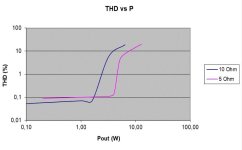
Here is my measured output power vs distortion graph for 18 V supply and 5 and 10 ohms dummy load:

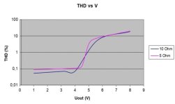
And, slightly more readable, the output voltage (rms) vs distortion graph, again with 18 V supply:

Up to slightly below 4 V distortion is dominated by H2 (good!).
Last edited:
accordung to ltspice my design has 12W worth of power outputPerfect, that's exactly what rod elliott recommends. The output power is not huge at 24 V supply, about 6 W with 8 ohm load.
Edit:
Here is my measured output power vs distortion graph for 18 V supply and 5 and 10 ohms dummy load:
View attachment 1372709
And, slightly more readable, the output voltage (rms) vs distortion graph, again with 18 V supply:
View attachment 1372710
Up to slightly below 4 V distortion is dominated by H2 (good!).
thats very little power. maybe i should use an op amp as an replacement for the front end circuitryPerfect, that's exactly what rod elliott recommends. The output power is not huge at 24 V supply, about 6 W with 8 ohm load.
Edit:
Here is my measured output power vs distortion graph for 18 V supply and 5 and 10 ohms dummy load:
View attachment 1372709
And, slightly more readable, the output voltage (rms) vs distortion graph, again with 18 V supply:
View attachment 1372710
Up to slightly below 4 V distortion is dominated by H2 (good!).
This is a proven Quasi design from the late 70's. It should be possible to mod it to run on a lower supply and to increase the bias stability. Its an unusual design but sounded really good. Single rail, AC coupled and so speaker safe. The circuitry at the top left is a slow start to minimise speaker thumps on power on.
LTspice file attached.
LTspice file attached.
Attachments
- Home
- Design & Build
- Electronic Design
- Overly simplified quasi complementary amplifier