More as an encouragement, and also to push the common imaginary boundaries in terms of parts and sound...
Roughly ahead:
A TO-220 generally sounds "better" than a TO-247. Cross-sections and shape are the main cause. The power and load specifications seem to discourage many audio enthusiasts from putting high loads on TO-220s. But don't worry: as always, first try;-)
It is also important to avoid connecting parts in parallel, as this leads to rounding and blurring of the sound. In addition, the practical layout of a paralleling is not considered by the vast majority, which in turn worsens the sound.
Here are two Single Ended to see: a BD711 (officially 75 watts and 12 A), a TO-220 power resistor and a trimmer each, at 35 VDC and > 2 amps. One input and one output capacitor. Nothing else. Sounds great;-) Although these BD711 are not audio suitable transistors.
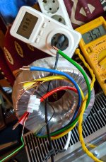
Transformer here > 800 watts. I have a few 150 mF, 35 VDC electrolytic capacitors. A changeover switch with a load resistor is suitable as a switch-on delay. Quite pragmatic;-)
The heat sink is of course somewhat larger, capable of cooling around 300 watts passively and many thousands of watts actively.
It may well be that a water cooling system with radiators as heat sinks is cheaper than the one you see. I think I presented such a system - for such large projects - here almost 20 years ago. If you use anodized aluminium, a mica plate could be omitted. I also have powder-coated heat sinks that make a mica disk unnecessary. Anyone who has ever experienced the difference in heat dissipation...-)
And the sound, the distortion behavior of the heat sinks also modulates the current, i.e. the signal, i.e. the sound. I would advise consideration here.
With such an amplifier (textbooks at the front;-) you can let off steam with parts and their sound. It is worth testing a large number of them to get maximum performance. Because don't forget: every part modulates the signal with its character, which is not indicated in lines and numbers;-)
What always will remain: a clear, clean, contoured, powerful, max. dynamic sound, not feasable with analog pp.
One day I want to try where the load ends, replace the load resistor with a transistor, build the thing balanced, maybe one or the other...
... 2 x TO-126 instead one TO-220;-?
I'll report;-)
But first of all, this thread has been started to encourage.
Roughly ahead:
A TO-220 generally sounds "better" than a TO-247. Cross-sections and shape are the main cause. The power and load specifications seem to discourage many audio enthusiasts from putting high loads on TO-220s. But don't worry: as always, first try;-)
It is also important to avoid connecting parts in parallel, as this leads to rounding and blurring of the sound. In addition, the practical layout of a paralleling is not considered by the vast majority, which in turn worsens the sound.
Here are two Single Ended to see: a BD711 (officially 75 watts and 12 A), a TO-220 power resistor and a trimmer each, at 35 VDC and > 2 amps. One input and one output capacitor. Nothing else. Sounds great;-) Although these BD711 are not audio suitable transistors.
Transformer here > 800 watts. I have a few 150 mF, 35 VDC electrolytic capacitors. A changeover switch with a load resistor is suitable as a switch-on delay. Quite pragmatic;-)
The heat sink is of course somewhat larger, capable of cooling around 300 watts passively and many thousands of watts actively.
It may well be that a water cooling system with radiators as heat sinks is cheaper than the one you see. I think I presented such a system - for such large projects - here almost 20 years ago. If you use anodized aluminium, a mica plate could be omitted. I also have powder-coated heat sinks that make a mica disk unnecessary. Anyone who has ever experienced the difference in heat dissipation...-)
And the sound, the distortion behavior of the heat sinks also modulates the current, i.e. the signal, i.e. the sound. I would advise consideration here.
With such an amplifier (textbooks at the front;-) you can let off steam with parts and their sound. It is worth testing a large number of them to get maximum performance. Because don't forget: every part modulates the signal with its character, which is not indicated in lines and numbers;-)
What always will remain: a clear, clean, contoured, powerful, max. dynamic sound, not feasable with analog pp.
One day I want to try where the load ends, replace the load resistor with a transistor, build the thing balanced, maybe one or the other...
... 2 x TO-126 instead one TO-220;-?
I'll report;-)
But first of all, this thread has been started to encourage.
Attachments
Last edited:
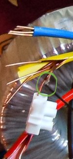
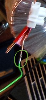
That picture (unintentionally?) reveals another secret of audio engineering.
Which is: Always follow the do not parallel rule.
Here: Use only one strand of an enameled litz wire.
Highly beneficial for the sound especially if it is an integral part of a mains transformer secondary winding.
/s
Which is: Always follow the do not parallel rule.
Here: Use only one strand of an enameled litz wire.
Highly beneficial for the sound especially if it is an integral part of a mains transformer secondary winding.
/s
Attachments
Last edited:

@cumbb
I find your contributions disconcerting. Either you want to make fun of us qualified engineers or you believe in the sermon you seem to be cultivating.
In principle, I welcome your experimental approach - but as a teacher, I would strongly recommend a guided framework. Ultimately, at the end of the day, a transfer should have been achieved, intellectually of course.
Perhaps you are a tinkerer? An inventor!
#
Let's work on a joint project, i.e. a cooperation between Lower Saxony and “?”.
Why don't you set up the EISENPORT and improve this idea with your specific audio engineering alone? According to your the well-known method of “listening measurements”.
Then I'll contribute a suitable PCB, maybe we'll even get rich selling kits worldwide.
greetings,
HBt.audio
I don't want to hide the fact that I have not yet come across a capacitor with high capacitance and electric strength that is also suitable for audio. But this project would needed them. The parallel connection of many small ones, such as PEG, 2 - 3 mF, would soften and smear the sound just as much as the parallel connection of transistors or diodes, for example. I do not recommend bridging with small capacitors, as this would audibly disfigure the sound, like a distorting mirror at a carnival.
An active power supply does a great job of smoothing out the voltage, and sound, but the sound characteristics of the components involved modulate the sound. Selected transistors suitable for audio would be an option.
As screen resistors use any TO-220 or TO126 type layer resistors also. For example, the standard wire-on-sand-in-ceramics are sonically inadequate.
A coil would be ideal: it not only smoothes, it also damps, filters. But by the way: even a coil does not conceal the sonic characteristics of the parts in front of it, such as power cables, plugs, switches, diodes, capacitors, fuses...
So don't be disappointed: such an amplifier is just for bigger stories that are not about the final truth - I still have my 2 meter tall dipoles with 12 X 12" full range;-) The majority will be better served and more satisfied with smaller SE amps or followers, max. 5 watts, in the home audio sector. A clean sound from the first "milliwatt" up to medium party levels. A PP concept can't do that - simply physics;-)-;
If a capacitor developer or manufacturer is reading this and is interested in developing and manufacturing large capacitors that are also current-compliant, i.e. suitable for audio, then...-)
(...)
So don't be disappointed: such an amplifier is just for bigger stories that are not about the final truth - I still have my 2 meter tall dipoles with 12 X 12" full range ;-) The majority will be better served and more satisfied with smaller SE amps or followers, max. 5 watts, in the home audio sector. A clean sound from the first "milliwatt" up to medium party levels. A PP concept can't do that - simply physics;-) -;
(...)
And we are supposed to fall for all this nonsense? Do you believe all the alternative crap you've spun together yourself or are you laughing at us followers - your fans?
With a kiss and goodbye,
HBt.audio
Psst
Alternatively,
you could provide concrete, mature, grown-up circuits.
40V_dc & 2A_dc
Is it true that we (want to) discuss this circuit?

One day I want to try where the load ends, replace the load resistor with a transistor, build the thing balanced, maybe one or the other...
... 2 x TO-126 instead one TO-220 ;-) ?
I'll report ;-) !
Is it true that we (want to) discuss this circuit?
I tried out what a BD711 can withstand. ONE channel only. It still runs on 100 volts. So nothing breaks that quickly;-)
But the question is whether it comes under audible stress under high voltage. I'm not going to test that today. This experience also comes from working with tubes. Also tubes have not been developed under audio aspects, and information about optimum voltages, for example, is too high with regard to audio. My experience is that 10 - 20 % below the data sheet optimum sounds more pleasant and cleaner.
The 100 volts here would of course tempt you to connect 4 or 5 of them in parallel;-) But even that would only make sense if you listened loud most of the time. A smaller big SE with, for example, 60 or 80 volts is completely sufficient for most situations. Then 2 - 3 in parallel, and you...-)
Attachments
Last edited:
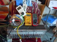
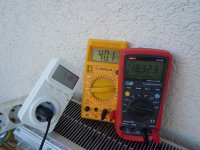
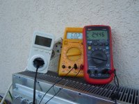
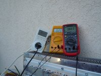
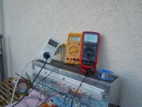
The power loss, a hyperbola!

What do your pictures show us?
Measuring device 1 - white
"Apparent power that you take from the lighting network"
[VA or W]
Measuring device 2 - yellow
"The total operating voltage, rectified, i.e. UCE plus RE"
[V_dc]
Measuring device 3 - red
"The collector-emitter voltage"
[V_dc]
Dear
@cumbb,
your posts are absolutely incomprehensible, they are confusing.
Please shed some light on your darkness.How big is your load resistance? Which voltage represents "yellow" and which "red"? How big is your load resistance?
#
Which voltage does "yellow" represent and which "red"?
If "yellow" stands for the sum of UCE + URE, and "red" for UCE, then you will always stay nice and under the hyperbola and everything will (still) be fine!
If "yellow" stands for UCE and "red" for URE, then you have had nothing but luck in the last image of your experiment.
#
I would like to tell you something else:
if you want to build a push-pull class B power amplifier and your rails stay just below +/-50Vdc, then you can use a pair to create just a 100W power amplifier (|Z| > 8 Ohm).
However, it won't be really reliable. The first decent bass impulse or a really sneaky test signal is the end of the game.
HBt.audio
Tell me:
Do I understand you correctly if all your test setups are primarily aimed at finding the "right sounding" component?
🙄
If this is the case, then you will unfortunately still not have achieved any results on the day of the call (when the Lord takes you to Himself).
I am very sorry to have to tell you this here,
HBt.
(not lucifer)
Psst
Last edited:
(...) Single Ended to see:
a BD711 (officially 75 watts and 12 A),
a TO-220 power resistor and a trimmer each, at 35 VDC and > 2 amps.
One input and one output capacitor. Nothing else.
Sounds great ;-) Although these BD711 are not audio suitable transistors.
So this BJT is not suitable,
why do you play with it and claim beforehand that "it sounds great" when it is actually useless in terms of audio technology? - As you said.
🤔☕
(Vcc/2) = UCEmax / ( 1+sqrt(5) ) = 31VdcMy experience is that 10 - 20 % below the data sheet optimum sounds more pleasant and cleaner.
The 100 volts here would of course (...)
Since nobody knows the optimum and can't do anything with this word, you could simply follow the formula above for Vce_peak. Experts will immediately recognize the "golden number" - this always helps when you have absolutely no idea how to proceed.
75VA / 31V = 2.42A represents the maximum permissible sinusoidal peak current?!
2.42Ap/2 ==> Iq= 1.21Adc
Since you absolutely want a single-cycle/ended circuit (and you mainly rave about JLH and Hiraga, we already know where the play is heading), we now immediately get the following values:
This leads to 10.24 true class A single-ended watts into a static, constant 8 ohms. P_loss = 2 * 1,6A * 31V = 99.2W_idle.
We would only need 12.8V+3V => +/-16V rails, but it is questionable whether this Vce is the optimum for the best soundquality. However, 10 * (16V / UCEmax) corresponds pretty much exactly to 1+sqrt(5) / 2 ... the "golden number".
#
What method or procedure do we now use to find the optimum operating voltage level?
Please help me @cumbb,
HBt.
Addendum:
Perhaps you would like to add the component values, component designation /choise, design as well as voltages, currents and temperatures by entering them in the sketch.

With the word temperature, i.e. heat (energy), it occurs to me that the guaranteed maximum values/ratings are of course temperature-dependent.
The warmer the poor amplifier gets, the less stress it will be able to withstand.
Remember,
the transistors must remain cold - sometimes, depending on the application and operating points, it can also be the case that a BJT must be kept constant at a very specific value (in this case the temperature).
Perhaps you would like to add the component values, component designation /choise, design as well as voltages, currents and temperatures by entering them in the sketch.
With the word temperature, i.e. heat (energy), it occurs to me that the guaranteed maximum values/ratings are of course temperature-dependent.
The warmer the poor amplifier gets, the less stress it will be able to withstand.
Remember,
the transistors must remain cold - sometimes, depending on the application and operating points, it can also be the case that a BJT must be kept constant at a very specific value (in this case the temperature).
It's probably cheating, but one could always grab a SiC MOSFET. Cheating, because it's likely a small low-voltage MOSFET with a large, HV JFET cascode stuck on top.
A SiC JFET would be more in keeping with strict Zen rules, if trying to avoid stacking too many transistors in series. (As Baldrick counts: 1, 2, many.) There was a Nelson Pass article from 2009-ish(?), which articulated the issue of stacking multiple gain stages, and then linearising the entire system with GNFB, likening it to a debt ponzi or something like that.
The way I understood it, say there are transistors A, B, and C, where the output + distortion from A is modulated by B, and then the combined output of B is further modulated by C. With n stages in the system, the "pure profit" of routing more gain into a feedback loop first has to account for a debt burden of modulation. Each additional stage makes the total distortion less harmonic and more dissonant in nature than the same system but with n-1 stages.
Douglas Self's (and related) 'blameless' and 'PPM' THD approaches seem promising and sensible at first glance. But it's basically:
"Let's have a gentleman's agreement that nothing can be heard below 'X' uV, so any kind of residual noise and distortion is fine, as long as it remains below that level."
That may or may not be desirable. If you're brave enough to plug in headphones to the speaker output, or, similarly, a 108dB/W horn tweeter for nearfield listening, that is likely to reveal all the crap / "subtle shortcomings".
Since a 100W power dissipation standard has been mentioned, how about 200V x 0.5A? Those special SiCFETs could probably be cryogenically cooled and put on blast if someone needs more amps.
Great Grandmasters ;-) use always ;-) +/-13Vdc, +/-21Vdc, +/-34Vdc or +/-55Vdc voltage rails for optimum soundquality in audible terms of audio engeneering ;-).
It's the golden rule of Leonardo Pisano,
the fibonacci audio company!
It's the golden rule of Leonardo Pisano,
the fibonacci audio company!
In some cases' I advice you ;-) use +34Vdc and -21Vdc
or
+21Vdc and -34Vdc ;-)
for
SE-WONDER-AMPLIFIERS
as
a rule of 👍. ;-).
or
+21Vdc and -34Vdc ;-)
for
SE-WONDER-AMPLIFIERS
as
a rule of 👍. ;-).
"Cross sections and shape" imply differing temperature gradients within the package. I'm surprised just a big 'ol heatsink is sufficient and a superior cooling solution isnt being sought. Luckily for all, the HP computer aficionados have created a market for that and an abundance of such cooling systems, componnets abound. It would be possible to hold the device temperature at whatever it is which produces the best sound, through closed loop control. As long as it's, say, below 100C...A TO-220 generally sounds "better" than a TO-247. Cross-sections and shape are the main cause.
- Status
- Not open for further replies.
- Home
- Amplifiers
- Solid State
- Single Ended, 40 VDC, 2 A, TO-220