Yes, the current flows in the same direction. But I explicitly mean the power. See, in signal cables the current is AC. So it flows in alternate directions. But the power is transferred in a single direction. From the source to the destination. For low power signal cables like from the turntable to the pre-amp or from the CD player to the pre-amp this is very very small. Like 100mV rms @ 47kOhm. Nevertheless, the audiophile sound quality experience differs enormously depending on whether the cables are connected in the right direction or in the opposite direction.The current flows in the same direction regardless of whether it’s EF or CFP.
In transistor amplifiers the DC current is unidirectional, but the power is clearly directed from the input to the output. While the leads are much shorter, the power levels are much larger. Like 10V rms @ 8 Ohms. I am really worried about that effect.
If you actually believe that direction of power flow (in engineering speak, the sign of the real part of VI*, where V and I are phasors) depends on the crystal orientation within the conductors then companies have really hit a gold mine with you.

Apparently satire does not carry well through internet.If you actually believe that direction of power flow (in engineering speak, the sign of the real part of VI*, where V and I are phasors) depends on the crystal orientation within the conductors then companies have really hit a gold mine with you.
I assumed my statements in post #38 were so bizarre no one would consider this anywhere near serious.
To state it again, it is totally audiophile nonsense what I wrote in post #38
With cumbb training you, one can’t possibly know what’s serious and what isn’t. Sounded to me like you took the words right out of his mouth. Hey, isn’t that Meat Loaf?
Yes 1979 IIRC. With Ellen Foley.With cumbb training you, one can’t possibly know what’s serious and what isn’t. Sounded to me like you took the words right out of his mouth. Hey, isn’t that Meat Loaf?
Hey I blamed internet for the satire not being recognized, not the reader 🙂
I blame the internet (or at least those who run it) for most of the evils in the world today.
Here is a small detail - attention: physics, "science"-)
The contact pressure of the transistor and resistor, here showing the resistor as an example, to the heat sink in order to achieve maximum thermal coupling.
I use screws here that press directly against the PN junctions. This is not possible using conventional housing screw connections or clips.
The contact pressure of the transistor and resistor, here showing the resistor as an example, to the heat sink in order to achieve maximum thermal coupling.
I use screws here that press directly against the PN junctions. This is not possible using conventional housing screw connections or clips.
Attachments
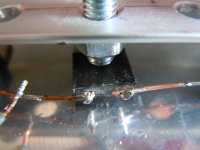
Are you serious? Ordinary galvanized soft steel. Do you have any idea how much the non-linear magnetic fields induced in the iron will affect the sound quality? The junction is literally millimeters away from the iron. Electron flow in the junction is also affected by the magnetic field from the iron bolt.I use screws here that press directly against the PN junctions. This is not possible using conventional housing screw connections or clips.
Of course you do - this is one idea that actually has good engineering basis behind it. It isn’t directly against the PN junction at all - there is certainly the epoxy case in the way. But direct pressure over the die area IS the best way to reduce thermal resistance, case to sink. The mounting hole in a TO-220 is in the wrong dam place from a thermal standpoint. And the tab really isn’t rigid enough either (it bends, leaving further voiding under the die).
Those solder joints however, would fall apart on a shaker table. Or perhaps just moving it around the workshop.
Those solder joints however, would fall apart on a shaker table. Or perhaps just moving it around the workshop.
Nothing revolutionary in this type of assembly which has been used in a few amps (not enough by the way) and I totally agree that it should be the standard.
Much simpler to implement on an assembly line.
Much simpler to implement on an assembly line.
Correct: this is a solder joint for an audio application: minimal solder, minimal cross-section, due to current definition, signal definition. Not designed for a shaker table and also not used in an UAZ for decades of operation in Mongolia or Russia;-)
By the way: even thick solder joints would crack under thermal expansion loads. In this case, I recommend laying the cable as a loop.
By the way: even thick solder joints would crack under thermal expansion loads. In this case, I recommend laying the cable as a loop.
Attachments

You are supposed to use minimal solder, but make a mechanical connection FIRST. A shaker table does, in fifteen seconds, what months of use in your HT subwoofer will. You do NOT want something critical to go open and send DC to your speaker. Especially the subwoofer.
Of course you do - this is one idea that actually has good engineering basis behind it. It isn’t directly against the PN junction at all - there is certainly the epoxy case in the way. But direct pressure over the die area IS the best way to reduce thermal resistance, case to sink. The mounting hole in a TO-220 is in the wrong dam place from a thermal standpoint. And the tab really isn’t rigid enough either (it bends, leaving further voiding under the die).
However, the TO220 backplate is made of copper which has a much better heat transfer than aluminum and using thermal grease should leave you without problems.
The thermal grease joint is physically THINNER with direct pressure. Even the copper lead frame deforms, and direct pressure deforms it in the right direction. Can a few tens of microns matter? YES. I’ve done the ANSYS thermal models and seen the IR results myself. As well as test data that confirms threshold voltage shift and reduced gain from thermal rise. Mind you, this was with RF power transistors (my day job, with a full lab at my disposal) but temperature is temperature.
As you can see, I make in application audio. And you in shaker tables;-)
I don't use thermal grease either.
I don't use thermal grease either.
My application is in audio too. The shaker table is just an industry standard way of doing an accelerated life test - they can’t wait months to see if something will vibrate apart under normal use.
I’m not putting something with a poor solder joint in one of my subwoofers, because I don’t want to pay for a RECONE or start a FIRE. I don’t need a shaker table to tell me when I see a questionable solder joint. When you start playing with 150 volt power supplies on your amps and something comes apart, things go szhekx in the night. You’ll quickly find out what 1/2 CV^2 means.
If the surface is flat enough, no thermal grease is better. If not, it can suck without it. Deformable and phase change interface materials are generally better and far easier to deal with, but the flattest possible dry joint is best short of eutectic attach. None of us here can get it that flat, and most AUDIO transistor packages aren’t up to that standard either. When you are dissipating 5 watts of average power it may not matter. Start adding zeros and it does.
Can you please link these two statements here?cumbb is the guy who tells everyone that mica sheets sound bad and that the transistor package matters more than the overall circuit.
A short sunday interim note:
In the search for a suitable TO-220 for a possible paralleling - I had received a gift from God, but I don't want to sacrifice it for such a paralleling project; it has to run solo! It shines and has a light; I have unpacked all my references, including the small, expensive JFets, and none of them can keep up;-) - I have now tested other transistors. I discovered a TIP-41C that could be a good choice, sound-wise. It has a "noise" track on the tones that makes it very present, so I hope that in a paralleling the "mark" in the sound will be preserved by this "noise", that the sound will not become rounded, doughy, greasy or lose contour as is typical of paralleling. I also cut it right away, which increases the dissolving. Now I just have to order a few dozen more and hope that no other batch is packed;-)
In the search for a suitable TO-220 for a possible paralleling - I had received a gift from God, but I don't want to sacrifice it for such a paralleling project; it has to run solo! It shines and has a light; I have unpacked all my references, including the small, expensive JFets, and none of them can keep up;-) - I have now tested other transistors. I discovered a TIP-41C that could be a good choice, sound-wise. It has a "noise" track on the tones that makes it very present, so I hope that in a paralleling the "mark" in the sound will be preserved by this "noise", that the sound will not become rounded, doughy, greasy or lose contour as is typical of paralleling. I also cut it right away, which increases the dissolving. Now I just have to order a few dozen more and hope that no other batch is packed;-)
- Status
- Not open for further replies.
- Home
- Amplifiers
- Solid State
- Single Ended, 40 VDC, 2 A, TO-220