The main cause for inrush current could be charging up large caps. This could be easily fixed by ramping the input voltage, much like a vacuum diode. No need for instant voltage on vacuum tubes.Are you sure of that reverse current? 180 mA sounds more like a forward current. D2 is just to discharge C1 when the regulator turns off. Without it you risk frying the regulator IC. It can be any diode. I use 1N4007.
The MOSFET needs to be able to survive the peak inrush power. I use a beefy SiC type in my current design, which is available here: https://neurochrome.com/products/21st-century-maida-regulator. But if you're planning for a lower output current, you could relax the requirements a bit.
Tom
You can certainly do that. But vacuum tube diodes tend to not have great reliability and they have a rather large forward voltage drop, so they may not be a good choice in all cases.
Tom
Tom
I know I'm late to the party, and you are probably done with this project by now, but I did run your .asc and found a problem with D4. Is this a 1N4001? Break downs at 50V.Hi Tom,
Here it is, this follow 21st century maida regulator schematic from this thread, When V1 set to 230V, Vout is 170 correctly but when i increase V1, Vout is no longer correct.
View attachment 1225140
Attachments
Oh. That's possible. Usually breakdown isn't modelled.
Either way. The 21st Century Maida is very much still going on. I'm currently out of stock, but I should have more within the next few weeks. It's been through quite a few updates since the original circuit. You can find it here: https://neurochrome.com/products/21st-century-maida-regulator
The real circuit uses 1N4007. 1 kV breakdown. 🙂
Tom
FOR DIY ONLY
With the above circuit i was able to get down to 2"/2" with integrated heat sink. Designed to be mounted to top panel with vents


With the above circuit i was able to get down to 2"/2" with integrated heat sink. Designed to be mounted to top panel with vents

The heat sink looks pretty small.
Also note that this is a vendor thread. I do offer a well-documented circuit that works: https://neurochrome.com/products/21st-century-maida-regulator
Tom
Also note that this is a vendor thread. I do offer a well-documented circuit that works: https://neurochrome.com/products/21st-century-maida-regulator
Tom
I can't find any LTspice sim files in this thread that provides any noticeable 120Hz rejection.
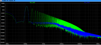
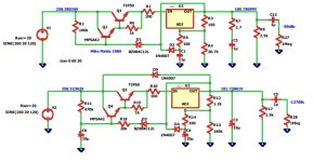
The original Mike Maida 1980 gives about 89dB of 120Hz rejection, adding small polarized 10uF cap and a 22k resistor, in the right places, improves it 38dB, and adds soft start. The TIP50 and MPSA42 limits the usable input to under 350V.
Using a HV MOSFET in lieu of the TIP50 the 120Hz rejection can be increased to 120dB, and ditching the the LM317 in favor of the old-ish LT1086 improves the rejection another 26dB.
The current limiting imposed by the FET-gate to output zener diode with the series resistor does not limit the the power dissipation on the FET, and adding a bipolar across the series resistor to limit the FET gate voltage just makes it into a constant current source, still with a major power dissipation on the FET.
I have a Mike Maida style reg in my power amps feeding the input and drivers and being a reference another regulator, for screen voltage. No plate regulation and no hum.
The LT3080 looks like a better part, my sims got it to very low nV output 120Hz, with an improved circuit, and over current protection that can turn off the FET entirely, or sent it into hiccup mode. Using a very high power FET to protect against mishaps also gives a harder to drive gate capacitance that negatively impact noise performance. A low gate charge seems to improve performance. The gate protection zener can be selected to include max current, no need for a 10A limit in a 100mA circuit.
I have the parts and the boards will be here shortly, I'll see how it pans out.
You can find the line rejection graph in the Performance Graphs tab of the Maida Reg product page: https://neurochrome.com/products/21st-century-maida-regulator. It's about 130 dB at 120 Hz.I can't find any LTspice sim files in this thread that provides any noticeable 120Hz rejection.
The original Maida Reg requires at least 10 mA in the feedback network to regulate. Mine requires much less. It runs at 2 mA. That means 1/5th the power dissipation in the feedback network.
Tom
I did find that, but not a sim file 🙁
Mike's original 44 year old LM317 design was very "low" voltage, he used a little under 10mA, newer regulators can handle well under 2mA.
The voltage divider resistors exposed to high voltage have to be designed for it. Power rating is not the only determinant for parts selection. I've replaced 2W metal film resistors in very expensive tube amps after a year in service. They became very noisy.
Attachments
Of course not. I don't publish schematics for my products. This is a vendor thread even though it started life as a DIY thread.I did find that, but not a sim file 🙁
Yep. And the resistors in the 21st Century Maida Reg. Rev. 3.1 were selected accordingly. I also made sure to have sufficient clearances in the PCB layout to ensure that the board will survive the high voltages.The voltage divider resistors exposed to high voltage have to be designed for it.
Tom
Anyone know the difference between the LT3080IT en -ET? Datasheet says they are both labeled -ET, but there has to be a reason they also have an -IT part number?
You gotta dig into the notes below the spec table on page 4:

So basically, the difference is in how the parts are tested. The 'E' grade is tested at room temperature and its performance is guaranteed within the range of 0 ºC to +125 ºC. Performance below freezing is assured (not guaranteed) by design, correlation, etc.
The performance of the 'I' grade is guaranteed across the full temperature range, which means the part has likely been tested at -40, +25, and +125 ºC.
Testing at temperatures below freezing is pretty expensive. In part, I think, because cold is more expensive to generate, but also because there tends to be more issues with cold testing, so it takes longer and, thus, is more expensive. The humidity in the air has this annoying tendency to freeze on the wafer and cold chuck and form ice. That mucks up the cold test.
Note that words like "guaranteed" and "assured" mean two very different things. "Guaranteed" is a legal term. If an 'I' grade part fails to meet the spec within -40ºC to +125 ºC it's a very big deal. The spec table is basically a legal agreement, and if they part doesn't meet spec, there could be legal trouble.
But if an 'E' grade part fails below freezing, it's "Oh, well. Sucks for you. Buy the more expensive 'I' grade next time".
The two grades are interchangeable in the Maida Regulator, assuming you're not operating it at -40 ºC. 🙂
Tom
Thanks for digging that up! If it gets below 0 here, I've got other problems to worry about than if my regulator will act up 😀 But I can see the use-cases outside of audio.
- Home
- Vendor's Bazaar
- 21st Century Maida Regulator