I tried their SPICE model but doesn't simulate as good. I got that 2N5551C model from somewhere can't remember where. Don't know how good it is, or if SMD parts die differs from TO-92 2N5551. I also tried MMBT5551 which is SOT-23 but same story, low performance overall.
Simulation does seem to show good performance with MPSA06 or BC550C but those are TO-92. I might try a few more SOT-23 BJTs with official SPICE models. But I do have some BC850C so I could have a go at it. Might be the high gain which helps.
Simulation does seem to show good performance with MPSA06 or BC550C but those are TO-92. I might try a few more SOT-23 BJTs with official SPICE models. But I do have some BC850C so I could have a go at it. Might be the high gain which helps.
You'll need to get a curve tracer and an fT meter so you can correlate SPICE results vs. real measurements on real transistors purchased in the real world from (it is hoped!) non counterfeit sellers. I was lucky enough to find a "BK Precision 530" fT meter at an amateur radio hobbyist site; there aren't many offered for sale but if you can find one, they are excellent.
_
_
Attachments

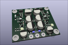
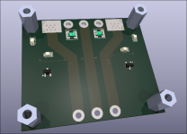
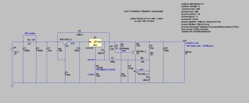
Seems like I can remove the double diode Vref and replace it with a single LED. Seems to work fine for 5Vout (bit lower performance but still pretty good), 12Vout and 30Vout. Though it needs a different LED configuration for 5Vout (IR Vref/IR CCS), 12V and up seems ok with Blue/Red LEDs combo. Also might be stable without compensation capacitor.
5Vout denoiser BJT runs a bit hotter at 11-12mA, the rest are ~8mA. Vref LED 4-5mA, CCS LED 1.5mA. Startup circuit 1mA.
All BJT SPICE models are Nexperia ones, BC850 seems like it does a decent job. MOSFET is SOIC-8 so should work fine on PCB, which by the way is even simpler, with alternate LED footprints on the backside.
Also forgot to mention, this discrete version needs around 150mV minimum across it, so you could potentially have 12.2V in and 12V out with some performance hit but not much.
@Mark Johnson Most of my parts are from one of the big online sellers, Farnell/Digikey/Mouser. That tester seems like nice gear but I'd rarely use such a thing. The fT graph seems interesting I'll try it myself with a few models, thanks!
Attachments

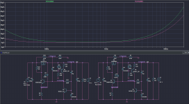
Seems like there are MPSA56/06 SOT-23 versions, Infineon SMBTA56/06. And their official SPICE models show good performance.
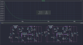
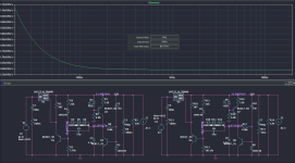
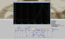
LTSpice PSRR graph for both positive/negative versions.

LTSpice PSRR graph for both positive/negative versions.
I haven't been following this thread nor read through the whole thing, but I've been promoting the following idea for a while. If you ever wished the negative circuit had as good a performance as the positive one (or vice versa), this may be of interest:
https://www.diyaudio.com/community/...d-lm337-regulators.143539/page-4#post-5111279
https://www.diyaudio.com/community/...d-lm337-regulators.143539/page-4#post-5111279
These types of regulators are in a whole other league than standard application for LM3x7. Even with the discrete version, there's some 10dB difference in PSRR which can easily be mitigated with pass transistor choice.
Regarding the LM3x7 versions, performance should be pretty similar for all intents and purposes. At least from simulation (but also from my measurements) they're as close as they get.
I attached a few performance metrics from simulation, photos in order:
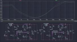
1. PSRR for both LM3x7
2. noise for LM317
3. noise for LM337
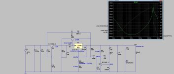
4. output impedance for both LM3x7
5. output impedance for the discrete version from previous post.
Any performance difference between them is basically irrelevant in practice.
Regarding the LM3x7 versions, performance should be pretty similar for all intents and purposes. At least from simulation (but also from my measurements) they're as close as they get.
I attached a few performance metrics from simulation, photos in order:
1. PSRR for both LM3x7
2. noise for LM317
3. noise for LM337
4. output impedance for both LM3x7
5. output impedance for the discrete version from previous post.
Any performance difference between them is basically irrelevant in practice.
Attachments

Last edited:
THANK you for such a cool addition. This "denoiser " ROCKS !!
(below) .
I built it on my breadboard , used my cheap LM317LZ 100mA TO-92's with a pass transistor.
- SO stable , so clean .... At least matches any "super regulator". I paired it with a cap multiplier .
I WILL design a +/- 12V regulator PCB with this design.
Super THANKS to the OP for this idea !!
PS - Swap the .Vnoise and AC directives in the simulation , -140db PSRR and 2nV noise.
A full 40db and 20nV better than without the "denoiser" !!! WOW !
OS
Attachments
Yup , even before I read this whole thread .... 😉 , my negative creation oscillated.
Higher currents triggered the oscillation - the current boosted 317 had too much gain.
I backtracked to a simpler (regular) 317/337 TO-220 pair with a phase margin tuned "denoiser" - added the CCS.
Margin can be tuned with the AC to DC denoiser gain ratio. CCS definitely added stability and
made use of my red led (for the CCS). Used a blue one with R7=390R as the negative side.
Way better than just a 317/337 pair and just as stable. (-140db and 2nV noise) .
Quite sufficient for my line stage and DAC PS's.
Still happy !!
NO MORE cheap eBay LMxxx regulator designs !!
PS - what attracted me to this thread is the sometimes poorly designed online "kits" (below)..
At least they hade the correct basic design with protection diodes and Sanyo electro's ... DO 1A+ with .1V regulation.
They are alright for just a sub amp predriver/filter or my breadboard PS. But NOT for my
Preamp - Headphone amp !!
OS
Attachments

Last edited:
470p is really too small as a compensation; 4n7 is the minimum recommended, and 10n is even safer.
And of course R8 should be 150K, but I imagine it is just a typo
And of course R8 should be 150K, but I imagine it is just a typo
Yup , even before I read this whole thread .... 😉 , my negative creation oscillated.
Higher currents triggered the oscillation - the current boosted 317 had too much gain.
I backtracked to a simpler (regular) 317/337 TO-220 pair with a phase margin tuned "denoiser" - added the CCS.
Margin can be tuned with the AC to DC denoiser gain ratio. CCS definitely added stability and
made use of my red led (for the CCS). Used a blue one with R7=390R as the negative side.
Way better than just a 317/337 pair and just as stable. (-140db and 2nV noise) .
Quite sufficient for my line stage and DAC PS's.
Still happy !!
NO MORE cheap eBay LMxxx regulator designs !!
PS - what attracted me to this thread is the sometimes poorly designed online "kits" (below)..
At least they hade the correct basic design with protection diodes and Sanyo electro's ... DO 1A+ with .1V regulation.
They are alright for just a sub amp predriver/filter or my breadboard PS. But NOT for my
Preamp - Headphone amp !!
OS
Can you add that CCS to a 337 version of the Denoiser? What about stability/oscillation? Did you build it instead of just breadboarding it?
The curve I get on LTSpice with this is a bit "weird", using your asc file.
There must be something else.CCS definitely added stability
Changing R8 2,2k to a CCS gives a higher gain denoiser, the effect is usually, less stability.
May be i missed something.
The CCS is strange , I think the plain 2.2k resister acts as just more DC+AC FB. The CCS isolates Q3 , so just the C8/R9 AC FB is active.Changing R8 2,2k to a CCS gives a higher gain denoiser, the effect is usually, less stability.
May be i missed something.
This whole "denoiser" setup seems to work like a Jung super regulator , but with the 317/337 acting as the op-amp/pass transistor.
No , I breadboarded it. Loaded it down with 22R - 10R and 8R ... all at -12V. Works nice , my scope showed a clean (not fuzzy) line at the right voltage.Can you add that CCS to a 337 version of the Denoiser? What about stability/oscillation? Did you build it instead of just breadboarding it?
317 and 337 also seem to be a bit better at voltage regulation , about .02V change.
I used a 4A bridge + 4700u , and a 50VA 20-0-20V antek trafo . The exact parts I will use when I do the finished product.
I don't have a model for the negative regulator , so no sim of that ??
Anybody have a LM337 model ?
OS
Breadboarding IS building it. Real parts , plugged into the wall ....breadboarding
Edit - I only rely on the simulator to "get close" , real parts tell the real truth.
OS
Q3 is an emitter common amplifier stage. A crude one with no emittor resistor, but that is fine here.
Changing the 2.2k to à CCS, changes the collector resistor to an infinite resistor. Hence more gain. I assume the CCS is biased to give 5.1mA same as with the 2.2k.
I assume R8 is 150k as seen by Elvee. A 150k makes sense to biais Q3, 150 is likely a typing mistake.
Re check Q3 biasing. Collector current and voltage, basé voltage.
Of course simulation is not the real thing. But extremely usefull.
The difficulty in regulator design when looking for high PSRR is stability.
Last edited:
Breadboarding is OK, and it is even more demanding than a good clean PCB: components wire are longer, layout is not optimum, etc.
It is a good stress test
It is a good stress test
OMG , really. I was using a "crippled" Denoiser (way less gain) ?? Yikes ! It still got -140.470p is really too small as a compensation; 4n7 is the minimum recommended, and 10n is even safer.
And of course R8 should be 150K, but I imagine it is just a typo
Yup ! better yet with 150 (K) , way more gain = -160db across the board ! Still stable , I used 100K on the breadboard .
A little better on noise (<1nV) , I HAVE to rely on the sim , my test equipment can't read that low anyway.
My mentioned oscillation issue was with a current boosted (triple EF) using the LM317(LZ).
LZ seems to have the same EF2 pass (below - circled) as the big 317A (to-220).
Cool !!
OS
Attachments
Simulation for noise is way off. For 12V output, noise density was measured to be about 8 nV.A little better on noise (<1nV) , I HAVE to rely on the sim , my test equipment can't read that low anyway.
https://www.diyaudio.com/community/...o-20v-1-5a-with-de-noiser.355883/post-6541296
One detail where simulation can give fake results is C10. It has ESR=0, such a capacitor doesn’t exist.
I think C10 >100uF is too much, I think 10uF at the regulator output is fine. Larger caps should be at the powered boards.
Simulate with realistic ESR, for trusty results. One can see with very low ESR, simulation results that can jump all over the place.
Fortunaltely real electrolytic caps have an ESR that is likely OK.
Just saying, it is better to know what is going on.
- Home
- Amplifiers
- Power Supplies
- D-Noizator: a magic active noise canceller to retrofit & upgrade any 317-based VReg