
Amazing chunk of effort here! Curious, I'm pretty sure the output filter of a class D amp "moves about" in its filtering performance with load impedance. It seems headphones can have a wider variation in load impedance presented to an amplifier than, say, speakers. A quick example I found on line "the Beyerdynamic DT 770 Pro , which has three variants - 32 ohms, 80 ohms and 250 ohms.,,,"
So let's say you designed for a particular headphone - your friends that presents a particular impedance load. Plug in a different headset and now the sound changes. Why? The headphones, or that the loading is a bit different. Some confounding there. I suppose an sufficient answer would be the design is for 32 ohm phones ONLY - different load impedances wont work correctly or as well.
So let's say you designed for a particular headphone - your friends that presents a particular impedance load. Plug in a different headset and now the sound changes. Why? The headphones, or that the loading is a bit different. Some confounding there. I suppose an sufficient answer would be the design is for 32 ohm phones ONLY - different load impedances wont work correctly or as well.
You raised a very important point. That’s why the base frequency of the PWM is set above 2MHz in the case, so the cutoff frequency of the filter can be very high. This way, the impact of load impedance changes on the LC filter’s performance is greatly reduced, and in most cases, can be ignored.Plug in a different headset and now the sound changes. Why?
5. Second version circuit and case design and test results
The first amplifier I built provided immense encouragement and sparked a strong desire to transform this achievement into a product for sharing with fellow music enthusiasts. Consequently, while designing the circuit board, I also created the amplifier's casing.
Improvements from the first version include utilizing a copy-and-paste method for both the left and right channels during the design process, ensuring strict uniformity. The upper and lower sections of the balanced circuit were also crafted with this method, maintaining perfect symmetry in wiring and component placement. According to the circuit simulation tool, the delay difference across all balanced lines is less than 1 picosecond. Additionally, each trace was routed in a smooth manner to guarantee consistent impedance and smoothness, thereby enhancing signal integrity.
Figure 1 displays the final circuit board design. Unfortunately, the saved file for the second version was lost, but the final version (fourth edition) retains the same overall layout as the second version, with only minor adjustments. The circuit board has been upgraded to a 6-layer design, ensuring that wherever necessary, all traces are surrounded by ground to minimize crosstalk between signals as much as possible. Figure 2 illustrates some details of the processed circuit board.

Figure 1, the final version of the circuit design

Figure 2, some details of the amplifier circuit board
The second version of the circuit board adopted a partitioned isolation design with a total of 11 independent sections. These include separate partitions for the power supply and main amplifier, left and right channel amplifiers, as well as different functional modules within the amplifier. Adequate spacing was reserved between these sections on the circuit board, and corresponding independent chambers were machined inside the inner casing. The circuits with different functions were placed in their respective chambers to eliminate interference between the circuits and block external signal interference.
This design approach maximizes consistency between the actual circuit and the simulation, thereby reducing the degree of performance degradation from the simulation results.
Due to my technical background, the design philosophy prioritizes performance, but I did not compromise on the aesthetic and tactile design either. Figure 3 shows the overall design concept of the circuit board, inner casing, and outer casing. The inner casing is made of high-grade aerospace aluminum, processed through CNC machining, while the outer casing is crafted from premium wood, which was meticulously polished by hand.

Figure 3, Structural design 3D and assembly diagram
Figure 4 and Figure 5 are the rendered design images and the actual sample photos, respectively.

Figure 4,Design rendering image

Figure 5,photo of prototype
Figure 6 displays the THD test results of the amplifier sample at frequencies of 600Hz, 1kHz, 2kHz, 3kHz, 4kHz, and 8kHz, with all measurements showing a distortion rate of 0.001%. This result has reached the limits of the testing equipment, indicating that the actual distortion of the amplifier is likely lower than 0.001%.

Figure 6, THD test results
Seeing these test results filled me with excitement. This is the first no-feedback audio amplifier to achieve such a low distortion rate. I believe there’s still room for improvement, and I plan to refine it gradually over time.
Now, I’d like to share my personal listening experience with this no-feedback Class D headphone amplifier. If you’re interested in trying it out, please reach out to me. I currently have a few samples available for music enthusiasts to test for free. In the future, I plan to initiate a crowdfunding campaign on well-known platforms for small-scale trial production, provided there’s enough interest from friends.
The first amplifier I built provided immense encouragement and sparked a strong desire to transform this achievement into a product for sharing with fellow music enthusiasts. Consequently, while designing the circuit board, I also created the amplifier's casing.
Improvements from the first version include utilizing a copy-and-paste method for both the left and right channels during the design process, ensuring strict uniformity. The upper and lower sections of the balanced circuit were also crafted with this method, maintaining perfect symmetry in wiring and component placement. According to the circuit simulation tool, the delay difference across all balanced lines is less than 1 picosecond. Additionally, each trace was routed in a smooth manner to guarantee consistent impedance and smoothness, thereby enhancing signal integrity.
Figure 1 displays the final circuit board design. Unfortunately, the saved file for the second version was lost, but the final version (fourth edition) retains the same overall layout as the second version, with only minor adjustments. The circuit board has been upgraded to a 6-layer design, ensuring that wherever necessary, all traces are surrounded by ground to minimize crosstalk between signals as much as possible. Figure 2 illustrates some details of the processed circuit board.
Figure 1, the final version of the circuit design
Figure 2, some details of the amplifier circuit board
The second version of the circuit board adopted a partitioned isolation design with a total of 11 independent sections. These include separate partitions for the power supply and main amplifier, left and right channel amplifiers, as well as different functional modules within the amplifier. Adequate spacing was reserved between these sections on the circuit board, and corresponding independent chambers were machined inside the inner casing. The circuits with different functions were placed in their respective chambers to eliminate interference between the circuits and block external signal interference.
This design approach maximizes consistency between the actual circuit and the simulation, thereby reducing the degree of performance degradation from the simulation results.
Due to my technical background, the design philosophy prioritizes performance, but I did not compromise on the aesthetic and tactile design either. Figure 3 shows the overall design concept of the circuit board, inner casing, and outer casing. The inner casing is made of high-grade aerospace aluminum, processed through CNC machining, while the outer casing is crafted from premium wood, which was meticulously polished by hand.
Figure 3, Structural design 3D and assembly diagram
Figure 4 and Figure 5 are the rendered design images and the actual sample photos, respectively.
Figure 4,Design rendering image
Figure 5,photo of prototype
Figure 6 displays the THD test results of the amplifier sample at frequencies of 600Hz, 1kHz, 2kHz, 3kHz, 4kHz, and 8kHz, with all measurements showing a distortion rate of 0.001%. This result has reached the limits of the testing equipment, indicating that the actual distortion of the amplifier is likely lower than 0.001%.
Figure 6, THD test results
Seeing these test results filled me with excitement. This is the first no-feedback audio amplifier to achieve such a low distortion rate. I believe there’s still room for improvement, and I plan to refine it gradually over time.
Now, I’d like to share my personal listening experience with this no-feedback Class D headphone amplifier. If you’re interested in trying it out, please reach out to me. I currently have a few samples available for music enthusiasts to test for free. In the future, I plan to initiate a crowdfunding campaign on well-known platforms for small-scale trial production, provided there’s enough interest from friends.

I would recommend to make some with 4.4mm pentaconn (balanced) input and output because many portable sources, especially the best ones, have better performance through their 4.4mm output vs 3.5mm output and many headphone/iem users have adjusted getting 4.4mm jacks for their phones. Also I would recommend to show the output power for different z loads as they can vary a lot with headphones like giving power ratings for 8, 16, 32, 80, 150, 300 ohm loads and the difference in gain between high and low.
Thank you for your suggestion. The input and output will support balanced connections, but due to the compact size of the portable amplifier, a 4-pole 3.5mm connector has been chosen.
As for the power, the output stage utilizes a full bridge configuration powered by 12V, delivering 150mW to a 600-ohm load, with increased power available for lower impedance loads. I use this amplifier to drive a pair of small bookshelf speakers, and it produces a great sound in a relatively small room.
As for the power, the output stage utilizes a full bridge configuration powered by 12V, delivering 150mW to a 600-ohm load, with increased power available for lower impedance loads. I use this amplifier to drive a pair of small bookshelf speakers, and it produces a great sound in a relatively small room.
You show this standard pre-filter global feedback class D design, but earlier you said you didn't want to use any feedback. Did you change your mind, if so why?Figure 2, Co

Figure 3, Multistage Half-Bridge Sigma-Delta Modulator with Schmitt Trigger Mechanism
I'm also confused with some of your goals. You said you wanted greater transparency, but also rich harmonics, distinct character iirc. That's conflicting.
Not to detract from your great results though.
Jan
for Jan.the feedback resistor R3 is applied to the output pulse signal only, which is part of the self-oscillating circuit. However, for the audio signal path, the loop remains open
//
@jan, you’re right—rich harmonics and transparency might conflict. Could you let me know in which paragraph I mentioned that? I searched the entire thread using the keyword "harmonic" and found only two results.I'm also confused with some of your goals. You said you wanted greater transparency, but also rich harmonics, distinct character iirc. That's conflicting.
Not to detract from your great results though.
There is audio coming out of the filter. The filter attenuates frequencies above the audio range but does not (ideally) do anything to the audio. Ergo, the audio is at the input of the filter. It has to be; if it is not at the input, it cannot coming out of it.for Jan.
//
And that is where the feedback is taken off.
Jan
Perhaps better you quote it 🙂It is in de very first post.
Jan
//
I don't know what is meant, only what is written, sorry.
Pleasant, warm harmonic content and distinctive tonal quality is at odds with transparency.
Transparent means that the music comes out as it comes in, nothing added, nothing taken away.
No distinct tonal quality, no warmed-up content.
As I said, this design is a nice one, I'm just commenting at the contradictory initial goals.
And it is perfectly normal to adjust your design ideas and goals as you go along.
"No plan survives first contact with the enemy" .
Jan
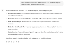
The list describes properties of sound if distortion is low - this is how I read it. And then presents the properties of the resulting sound if this is the case...
e.g.: When distortion is low..... the sound typically has ..... rich harmonics.
I think he means that reproduction can convey rich harmonics. Its not the amp that is rich...
But language.... "has", "provides", "more" .... is it the amp itself or is it the recording that is more faithfully reproduces... well.... 🙂 its not totally clear...
Looks like I just glossed over this first part - doyee!
Seeing it again in the above examination, I'd have to say "low levels of distortion" dont "contribute" anything. Which, kinda invalidates the "Rich Harmonics" bullet in my mind anyway. If gravy were rich, it would have a lot of complexity to its taste; low levels of distortion sounds more like distilled water...
Transparency, Dynamic Range, Stable Imaging make intuitive sense for a "no feedback" design, in my distorted perception of how things work anyway. Still, even though I believe I was shown to be wrong in that way of thinking here.
Distinctive Tonal Quality seems like an attribute of tube amplification and transformer coupling, unless its being thought of as the Quality of the absence of any / all that. I suppose distilled water could have a distinctive taste via the absence of any.
The feedback taken before the filter; is it just the pulse edge to get the circuit to oscillate? I wonder how the op-amp would subtract an ultrasonic pulse train from the audio frequencies, without that pulse train being integrated somewhere along the way? Is that happening in the low pass slope of the op-amp's bandwidth; the pulses being so gigantic in amplitude leak through that integration just enough to trigger oscillation?
The title of this entire thread should remove "Zero Feedback". Clearly the author has no understanding of what feedback is. This amplifier is based on the highest amount of global feedback that can be applied as that is the fundamental basis for the sigma-delta modulator. The loop is indeed closed for the audio signal path. This can be demonstrated by the fact that this design will have a low output impedance as the feedback of the audio signal adjusts the modulation as the load changes. The power supply rejection would also be the result of feedback.Thank you for your questions.
Regarding the first point, I believe it is acceptable to call it a sigma-delta modulator.
As for the second point, the feedback resistor R3 is applied to the output pulse signal only, which is part of the self-oscillating circuit. However, for the audio signal path, the loop remains open.
It is likely a nice amplifier, with great build quality and great sound, but it is a total work of fiction to call it zero feedback. The initial schematics with the simple PWM based on the triangle wave had zero feedback and those designs would have high output impedance and zero PSRR.
- Home
- Amplifiers
- Class D
- The Journey of DIY No-Feedback Class D Amplifier (1) Subtitle: The Motivation and Story Behind It