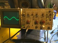
I rebuilt this amp and am now getting high frequency oscillation at the highest frequency well above the audible range. I have to have my 60MHz scope on the highest frequency setting to see it. It is in both channels but worse on one side. And the unit has to warm up for ~10 or so minutes before the issue starts.
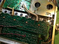
Output transistors were replaced with 2SC5200/compliment. I had to mount the outputs for one channel sideways and use leads to connect them to the board. Not the sort of thing I like to do, but I couldn't find any alternative. The original batwing outputs are obsolete and the transformer plate is in the way of installing the TO-3P straight.
Driver transistors are original. I replaced the input transistors with KSC1845s and 992s.
I also replaced the 10ohm resistors in the stability network (R1/R2 on PS/protect board), as one was damaged. I replaced the associated 0.082uF caps as well.
Any ideas? I'm regretting taking this job on now. These are finnicky circuits and the original outputs are unique.
Attachments
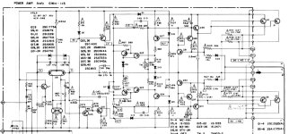
Try removing both C49 and C51. If that makes it stable, just leave them out.
If that does not help, try readjusting the R67 and C41 network across the output of the input stage.
If that does not help, try readjusting the R67 and C41 network across the output of the input stage.
Would you be able to share with us what the purpose of these capacitors purpose is, why you suspect them to be causing issue, and your steps to arrive there? Perhaps the same for the latter recommendation.Try removing both C49 and C51. If that makes it stable, just leave them out.
If that does not help, try readjusting the R67 and C41 network across the output of the input stage.
To my knowledge, C49 and C51 are actually there to prevent oscillations by acting as a high pass filter for frequencies that would cause issues, shunting out the resistor for those currents that are present at such high frequency.
C49 and C51 are "peaking capacitors" which attempt to compensate for the following load capacitance.
This approach was very popular in older ss and tube designs, until it wasn't. They were tuned to the devices used.
Also be sure the replaced output Zobel has low inductance parts, or its function will be impaired.
This approach was very popular in older ss and tube designs, until it wasn't. They were tuned to the devices used.
Also be sure the replaced output Zobel has low inductance parts, or its function will be impaired.
For a amp circuit with such a non-standard topology , I would simulate it. Check phase margin/ gain.
You seem to have a close gain/Ft match for your new outputs.
Input pairs might be different , play around with (lag - C41 + R67 470R) , up C41 to 220-330p. You might have too much OLG now.
just a guess , build it in LTspice.
Edit - most stages are similar to my sonance 260 lag... C41-300p , R67 -470R .... lead comp. C45 = 15p That gives about 600Khz UG
with at least 50 deg. margin (stable).
OS
Last edited:
After the VAS looks like a non-switching AB circuit ??
Not sure how that would affect the circuit comp. ??
OS
Not sure how that would affect the circuit comp. ??
OS
So compensation values could need to be changed as suggested.
Another thought was depending on original fault
If both channels were shorted or fault occurred.
The amplifier is now " working"
But flyback voltages might have taking out components in the VI limiters or bias section.
So amplifier could be working but their may be other damaged devices causing stability issues.
They are not always active so amplifier works. But damaged diodes, Zeners or even transistors in the VI limiters
Could be or known to cause problems even after the power section is repaired.
Double check diodes, Zener and few transistors in the VI limiters and strange setup around the thermistor
When a amp faults and VI limiters grap, the flyback voltage although very quick is often 5x or more higher
So diodes zeners transistors even caps get damaged since the quick voltage is much much higher than the rating.
Sometimes completely dead or often give strange readings and appear working.
Only one channel was blown, but I rebuilt both to match.
The channel that was blown is the one with the worse oscillation. Though that could be a coincidence.
It is interesting how it has to warm up for the issue to start. Does that tell us anything?
The channel that was blown is the one with the worse oscillation. Though that could be a coincidence.
It is interesting how it has to warm up for the issue to start. Does that tell us anything?
Does the actual voltages and currents in the amp match those specified in the diagrams. I remember replacing parts in my old SA8100 due to excessive white noise developing in one channel of the amp with modern low noise high FT transistors caused havoc.
I eventually sourced components from eBay that was removed from other old Pioneer amps and the problem was gone. Never the less a few years later the problem started again, knowing what I had to endure, and I did not want to go through this long and costly process again.
Since it was my own amp and I liked the look of it, I decided to measure the PCBs positions of power transistors and mounting hardware and designed my own amp trying to contain the warm sound (far less complex) and replaced both circuits with my own.
I was very pleased with the results and to be honest, it sounded the same (or maybe even better) because it looked the same. I think the SA8100/9100 amps where some of the most beautiful amps that was ever made.
The SA8100 was sold with much regret to a friend nagging me to buy it for years and I have never recovered from my loss, it was like losing a family member.
Being made in the 70s, there are probably a lot more that went wrong besides transistors or caps or diodes or solder joints or corrosion, etc. The fact is it served for almost 50 years. It cannot last forever. Listen to Freddy Mercury (Queen) you can't live forever. The amp that I replaced it with was a Lateral MOSFET design that had the same warmish sound. You will be happy after the change knowing that it won't fail for another 50 years.
The amp I based the "new" PCB design on was from Hitachi application notes from the 2SK1058/2SK162 data sheets.
Last edited:
I changed C41 to 330pF and R67 to 470ohm. It seems to be happy now. Should I change C45 to 15pF as well?For a amp circuit with such a non-standard topology , I would simulate it. Check phase margin/ gain.
You seem to have a close gain/Ft match for your new outputs.
Input pairs might be different , play around with (lag - C41 + R67 470R) , up C41 to 220-330p. You might have too much OLG now.
just a guess , build it in LTspice.
Edit - most stages are similar to my sonance 260 lag... C41-300p , R67 -470R .... lead comp. C45 = 15p That gives about 600Khz UG
with at least 50 deg. margin (stable).
OS
This thing has a two stage bias adjustment. The first adjustment sets the bias to 56mV then the second one sets it to 70. With the new parts, the bias is at 70 with the second control all the way down. Is this an issue? Does only the final bias matter, or do both stages need to be set correctly?
Can I tweak the circuit to compensate?
I think that R9 isn't the bias setting but the Non Switching point setting as OS mentioned already.
If so you need an input signal for this adjustment.
Try to find the service manual.
If so you need an input signal for this adjustment.
Try to find the service manual.
Yes , our DIY amps seem to turn out both better behaved plus better sounding.Since it was my own amp and I liked the look of it, I decided to measure the PCBs positions of power transistors and mounting hardware and designed my own amp trying to contain the warm sound (far less complex) and replaced both circuits with my own.
My personal (DIY) amp runs the coolest , everything is so over-rated (2X) the voltage and current derated , the parts are "barely working"....
I even run my output stage at the coolest bias. Nothing ever strains sipping at 60-100KuF of toroid DC power.
As DIY , we can replace the "$$bottom line$$" with better parts/designs.
Attachments

Is anyone able to shed some light on the bias circuit?I changed C41 to 330pF and R67 to 470ohm. It seems to be happy now. Should I change C45 to 15pF as well?
This thing has a two stage bias adjustment. The first adjustment sets the bias to 56mV then the second one sets it to 70. With the new parts, the bias is at 70 with the second control all the way down. Is this an issue? Does only the final bias matter, or do both stages need to be set correctly?
Can I tweak the circuit to compensate?
Do both stages need to be set correctly, or is only the final bias important?
How can I tweak the circuit to lower the bias range?
Sorry to bump this again, I'm a bit desparate for an answer as it would be a shame to get the oscillation issue solved and then not be able to bias this thing correctly...
Does anyone here understand the two stage bias circuit? My last 3 posts explain the issue.
Any help would be much appreciated.
Does anyone here understand the two stage bias circuit? My last 3 posts explain the issue.
Any help would be much appreciated.
- Home
- Amplifiers
- Solid State
- Pioneer SA-8800 HF oscillation after rebuild