You most definitely don't need 120dB for a occasional party.I have closed box woofers in my own system as I don't need 120db
Unless that's an entire village, ..... maybe
Also keep in mind that party level only needs about 30-40Hz -3dB or so
I would just do a closed vs ported system
Just EQ the rest, sounds like there will be tons of headroom to do that.
Although I can probably already guess it has to be passive once again 🙁
Knowing what people do during parties, I would never use my main system for that to begin with.
Anyway, it's rather offtopic.
Previous party had more people than the village, about 50 😀 It's big mansion type of place in countryside and the people living there are record collectors and fond of good hifi night clubs, and plan is to provide some of that in their home.
It's DSP with FIR and I'll make different setups for both in door and outdoor party, as well as the winter time hifi listening sitting. 120dB / 1 meter is only 102dB / 8m so perhaps 90db with headroom so while it seems much I think it's lost outdoors quite fast. The system isn't likely played at max but the ethos is to have as much headroom as possible for best possible sound at comfortably loud level. Mid top is two way 15" with 1.4" driver in 52cm freetanding waveguide and can do the hifi thing without the subs although without the bottom octave, which I plan to fill in with the subs.
Initial plan was with four subs and MEH top but the budget shrunk critical amount so trying to make it as good as possible with the budget 🙂
Last edited:

useful values are between 0,15 - 0,5
Thank you for responding to my question on really high NFR values
For NFR values I think your quote above is a much better analysis than the Salvatti et al claim that 1.5 is the optimum compromise. Their paper certainly lacks the necessary math to support that claim.
Given all the reasons you have stated in your response. I would say it is likely that “0.15 and 0.5 are approximate points of diminishing returns for NFR“ rather than “0.5 is a global peak in performance”, admittedly also without the necessary calculus . . .
In ”fuzzy” language “values outside of this range are probably not worth the effort, but what is best in your case depends.”
This may seem pedantic to non-professionals, but I am worried that people will see ”Salvatti says NFR = 0.5 is best”, ignore all of the more complicated work and explanation you have provided and not make full use of the tools you are giving us.
Hi tmuikku, a few thoughts from having built several 18" ported subs...
For a single 18", I would not build with two slotted ports. If I wanted to use slotted ports, I'd build a single port.
Reasons being, two ports takes more wood, more construction complexity, and will result in a larger/heavier box.
I know you want height, but the longer any internal dimensions are inside the sub, the greater the resonance issues ime.
A great way to add height, is to put permanent castor wheels under the box. And makes it easy to move around for party mode 😀
I use 6" wheels that lock under mine.
My favorite single 18" box style is 4 triangular corner ports. Takes one piece of wood to form each port, and most importantly, they make wonderful braces.
The also equalize pressure to driver cone. The sum area of the 4 corner ports behaves like a little less area than one big slot port. I'd add maybe 10-15% total area vs one port. Had to have too much port, if you have the room for necessary length. Length measure a little bit longer than one port.
Whether single slot port or corner ports, as long as I've kept Peak Particle velocity below 25 m/s, I've had no port noise issues.
This is again for 18", where post area is 40+% of Sd, and length is tuned for maximally flat.
No real radiuses to speak of, other than round over bits on the 3/4" ply.
@stv,
thank you so much for all the work you've been doing and sharing. Bringing our attention to Strouhal number, and getting Strouhal into Hornresp along with your calculator, rocks !
I just reran Hornresp for the latest sub I've built, a double 18" ported, to check out Strouhal at max displacement. I haven't read deep enough into the thread to know where this value stands...I just know the port at 43% Sd and 60cm long works well.
Oops
Sorry, I meant to say “Salvatti et al claim that 0.5 is the optimum compromise”
Salvatti et al claim that 1.5 is the optimum compromise.
Sorry, I meant to say “Salvatti et al claim that 0.5 is the optimum compromise”
Thank you for the kind words!I haven't read deep enough into the thread to know where this value stands...I just know the port at 43% Sd and 60cm long works well.
The Roozen paper states that keeping Strouhal number above 1 avoids turbulent flow separation.
My tests indicated that for long ports (Lenth/min-diameter ratio > 6) this is indeed correct.
For shorter ports it is better to keep strouhal number above 1.5 - 2 to avoid turbulent flow and strong compression effects.
exactly!In ”fuzzy” language “values outside of this range are probably not worth the effort, but what is best in your case depends.”
We also reach a limit for predictions and simulations, because of the very simplified models and the increasing influence of several other factors.
Thanks, that's probably too much praise for me!your quote above is a much better analysis than the Salvatti et al claim
I am just standing on the shoulders of giants (one of whom is Salvatti!)
I'll try to show a sensible method, using my latest findings.stv, ok how would you design a port for a speaker, what's your procedure?
1. modeling the desired speaker response
I would first model the desired enclosure and tuning, just as you did in Vituixcad, still without considering the port air speed or strouhal numbers.2. finding a suitable port mouth size to keep strouhal number in a safe range
I would then switch to hornresp for convenience, because it can output strouhal number graphs directly in the loudspeaker wizard.It is still possible to calculate the strouhal number using the air velocity data, the tuning frequency and the port radius, see here.
The helmholtz resonator tuning and the (isolated) port output calculation is independent from the driver by the way (I just take one I have a hornresp model for and raised the input voltage to reach 125 dB, defining a 2pi radiation - I suppose the sub will stand on the floor).
your specified data:
volume: 250 l
tuning: 33,2 Hz
desired output: 125 dB/1m

I used your values for the port and (surprise!) the tuning in hornresp is exaclty the same. But hornresp also shows the resonances that a 40 cm deep undampened enclosure will produce (I just took an arbitrary depth value).
Now I switch to the port air velocity graph and press Ctrl and click twice for the Strouhal graph (thank you once more, @David McBean!):

The strouhal number remains just above 1.5 at all frequencies - that's perfect!
If the graph would go below 1.5 I would simply increase the port surface slightly while keeping the tuning at 33.2 Hz by adjusting port length.
Increasing the port surface increases the port radius (thus increasing the strouhal number) and at the same time it lowers the air displacement which also increases strouhal number. So usually a small change will be enough.
3. finding a suitable port geometry (just as you did)
now I use the excel tool and try to find a suitable port geometry.Because of the big volume the port is relatively short and any NFR number will still keep minimum port diameter quite wide.
In this case I would stick to the suggested NFR=0,.5 value by Salvatti/Devantier/Button, because they had similar Lact/Dmin ratios between 1.75-2.
An even higher NFR value might be usable - I measured one port with NFR=1 and a Lact/Dmin=0,53 (sony rounded hole port. this port allowed a low strouhal number below 1 without much compression).
The low Lact/Dmin ratio also means that you don't have to worry about the middle port strouhal number (MPSN) - it will alway stay high enough to be safe.
Just to check:
Amin/Amax = 53,6% (sorry, in the excel sheet the calculation is correct, but the designation is wrong, will be corrected!)
STROUHAL NUMBER = 1,5
MID PORT STROUHAL NUMBER = 1,5 * 53,6% * 100 = 80
that's very safe as I measured in my tests. Also see the same posting regarding my definition of MPSN.
In other words: The limiting factor for this port is the transition from pressurized volume to accelerated port air and vice-versa,
not the middle port section (wide in this case).
So that's exactly what you did:
Dext = 30 cm (effective exterior diameter, will be widened slightly with the roundover)
NFR = 0.5
Lact = 30 cm (actual built length of the port)
Tuning = 33 Hz
Dmin = 21,96 cm (minimum diameter at the port middle section)
r round = 4,39 cm (roundover radius for port end transition to baffle and internal flange)
you could build this port using these parameters. you could use respective Freecad model and Fusion360 model, The wall thicknesses may need to be adjusted for your big ports!
4. changing it to two ports (again very similar to your method)
As i wrote earlier, you could just make two ports with the same length and half the surfaces each:original port:
lenght = 30 cm
Amax = 707 cm2
Amin = 379 cm2
Now you can replicate a port with half the surface areas (the NFR will have to change!), without paying attention to the tuning:
one of two ports for similar tuning:
length = 30 cm
A max = 707/2 cm2 = 353,5 cm2
A min = 379/2 cm2 = 189,5 cm2
that leads to:
Dext = 21,2 cm .... you could also simply calculate 30/sqrt(2)
now I adjust the NFR to adjust Amin = 189,5 cm2
and get
NFR = 0,365
I you stuff one of those ports you will get the tuning as calculated by the excel sheet with this values: 24 Hz (the salvatti value!)
(That's quite near the one-port result of 23,3 Hz you got in Vituixcad, by the way).
As you did with your method you could now increase the NFR again, to further reduce the port lenght slightly:
Dext remains the same = 21,2
Tuning shall remain at 24 Hz (salvatti value, not the corrected one)
NFR increased to 0.5
Lenght needs to be reduced to ....
... 27 cm
(your calculation result of 28 cm is probably more exact!)
Its not easy to predict the exact behaviour and I have to say that I never built a speaker with such a SPL capability (yet).What is the difference in performance now? Is compression the same for one big port and two small ones now the same? What about distortion?
but I will try to make some educated guesses:
- If you use optimized geometry ports as defined above the difference between one or two ports will be much smaller than with straight tubes or slots. This is mainly because these ports are a lot less lossy and noisy.
- Behaviour of a rectangular or slot port with 2 or 4 rounded sides will be very similar.
- For a 3d-printed port use high infill numbers and a generous wall thickness. Around 8 mm should probably suffice, because all surfaces are curved in two dimensions, thus geometrically inherently stiff.
- Keep in mind that PLA is not resistant to heat. temperatures above 50-60° C will weaken the material significantly. I suggest to use wood for the final speaker, considering the high power you will driver the speaker with. Also the sun can quickly heat up the speaker's surfaces if used outside!
- Two optimized ports will behave WAAAAY better than one straight tube/slot port with similar mouth surface, and let's not even speak of two straight ports.
- Down to strouhal number of 1,5 I don't expect the ports to compress much more than 1,5 - 2 dB. The driver will probably compress much more due to voice coil heating at that level. For lower levels I expect virtually no compression at all.
- In all honesty I would not care at all about distortion numbers. The distortion of the port/s at tuning frequency will be WAAAAY lower than the driver itself allows for frequencies just sligthly above tuning. That's the case with virtually all bass reflex speakers, by the way. But apart from that at the low frequencies and at the levels you defined - I don't think anyone will hear the speaker distort, they will rather hear their ears' distortion. And for low levels (Hifi use) there won't be a trace of any distortion. I can guarantee you that!
The best way would certainly be to build a test enclosure with test ports and try it.
Or you make exchangeable panels for the final speaker, one with two ports, one big port or even a completely sealed one and have all the flexibility for testing and optimizing. Or make a flange system for different ports and lids.
Have fun and keep me updated!
Last edited:
I'll have to add a bunch of considerations regarding the two-port-option:What is the difference in performance now?
the strouhal number will be lower for two half surface ports. this can quickly and roughly be estimated with hornresp taking half the port surface and half the enclosure volume. The strouhal number is now below 1, indicating a higher tendency to compression and eventual noise. In order to compensate this I suggest to keep the port length as defined before and lowering the NFR. This should allow a more tolerant behaviour regarding low strouhal numbers.EDIT: I'll have to think more about this. I suppose also the driver input for such a "half box" would need to be halved, keeping the strouhal number at the original level. EDIT2: it's probably not that difficult: the displacement for two ports is essentially the same as for one big one (not considering boundary effects etc.). The radius decreases by 1/sqrt(2). Thus the strouhal number also decreases by a factor of 0,707. That's not that bad.- I would not overestimate the negative effects of two ports, following my tests with very slim slot-ports having a similar port suface/edge lenght ratio.
- If using only one port the strouhal number is getting very low, because of low tuning, higher "loading" of the single port and subsequent much higher displacement. Tuning is now around 25 Hz and the strouhal number is below 0.5 - but I guess this use case does not include 125 dB of output. Also, following my tests at very low frequencies the negative impact of low strouhal numbers is less severe.
If you discover anything interesting with your project, please let us know!
Last edited:
Wow, cool, thank you very much! Yes I'm going to build one first and with detachable panel so I can tweak the ports if necessary.
Good point about the heat! I'm planning to use PETG for prints, melting temperature 230-250C which should be enough. And thanks for printing tips, the ports are likely part of bracing so they should be strong for many reasons.
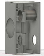
Driver is middle of the longest dimension to kill the first mode so one big port is tough to locate other than directly behind the driver, and likely emits all the driver noise. The two ports are positioned to reduce box modes leak, at least in theory, Keeping everything symmetric should keep the modes at bay.
Goal is very high performance, and it's about same amount of money and work in construction as any other similar size subs, if this planning stage is not counted in, so why not try 🙂 this is also my first high output system so let's see, many changes to do errors and learn.
Current sketch attached, I need to think more about the bracing, it's possible to make inlet of the ports terminate in panel just like the outputs, and there is good chance to do CLD with the bracing but need to first calculate how much plywood I need for the whole project and then cut sheets, and figure out how to put it together. Also driver could be mounted from behind and even the magnet could be secured to the structure if back panel is detachable.
Thanks again! I'll keep you posted after some results. The project spans several months though so might take some time before I get to measure.
Good point about the heat! I'm planning to use PETG for prints, melting temperature 230-250C which should be enough. And thanks for printing tips, the ports are likely part of bracing so they should be strong for many reasons.
Driver is middle of the longest dimension to kill the first mode so one big port is tough to locate other than directly behind the driver, and likely emits all the driver noise. The two ports are positioned to reduce box modes leak, at least in theory, Keeping everything symmetric should keep the modes at bay.
Goal is very high performance, and it's about same amount of money and work in construction as any other similar size subs, if this planning stage is not counted in, so why not try 🙂 this is also my first high output system so let's see, many changes to do errors and learn.
Current sketch attached, I need to think more about the bracing, it's possible to make inlet of the ports terminate in panel just like the outputs, and there is good chance to do CLD with the bracing but need to first calculate how much plywood I need for the whole project and then cut sheets, and figure out how to put it together. Also driver could be mounted from behind and even the magnet could be secured to the structure if back panel is detachable.
Thanks again! I'll keep you posted after some results. The project spans several months though so might take some time before I get to measure.
Attachments
Last edited:
That's good, because I will investigate further and may update the calculation tool for better usability.Thanks again! I'll keep you posted after some results. The project spans several months though so might take some time before I get to measure.
Happy and proud if my tool can be useful for such a challenging project!
Just a quick sign of life.
I am continuing to develop the Excel tool for flared (variable NFR) ports.
I think the tool lacked quite some usability.
So here are some planned improvements:
port geometry preview in the excel tool:

I am continuing to develop the Excel tool for flared (variable NFR) ports.
I think the tool lacked quite some usability.
So here are some planned improvements:
- the input of exterior port diameter and NFR is somewhat unintuitive. I will change it to exterior and minimum diameter input with calculation of resulting NFR.
- I tried to make a rough port section preview based on an excel point graph. this should give a quick feel for the port dimensions.
- input field for speed of sound will be less prominently placed, because it may lead to mix up with port air velocity.
- there will be an input field for maximum desired port output SPL at tuning frequency - keeping in mind that the total output will be slightly higher with the driver output added.
- based on the desired SPL and a formula posted here I will provide calculation of necessary air displacement and resulting max. port air speeds, strouhal number and MPSN at tuning frequency. I will add a comment stating that strouhal number will be slightly lower just below the tuning frequency (this can be observed in hornresp).
- I will provide warning messages for any dangerously high or low resulting value (e.g. max absolute air velocity limit of 30 m/s; min MPSN based on the port length/min-diameter relation between 20 and about 40). using these warnings it should be possible to adjust values to get a good behaving port geometry.
- metric and imperial versions will be included in the same file on two different spreadsheet tabs.
port geometry preview in the excel tool:
Last edited:
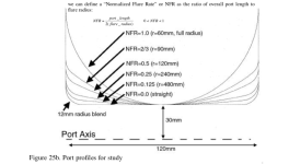
Most commercially available "flared ports" are straight with a radius at the end, a "Normalized Flare Rate" of "0".I am continuing to develop the Excel tool for flared (variable NFR) ports.
the input of exterior port diameter and NFR is somewhat unintuitive. I will change it to exterior and minimum diameter input with calculation of resulting NFR.
Appears you are eliminating the end radius, which changes the exterior port diameter as used in the AES paper" Maximizing Performance from loudspeaker Ports" that coined the "NFR" term.
Attachments
No, that's just a simplification of the excel graph - but I'll try to include it. Just needs some trigonometry to convince excel ...Appears you are eliminating the end radius,
Yes - and it's a pity, because higher NFR ports are so much better. But I know straight ports have the advantage to be adjustable to any length. But 3d-printing might be a solution.Most commercially available "flared ports" are straight with a radius at the end, a "Normalized Flare Rate" of "0".
Aren't you afraid of midrange leaks through ports? Or will this be a 3-way?Wow, cool, thank you very much! Yes I'm going to build one first and with detachable panel so I can tweak the ports if necessary.
Good point about the heat! I'm planning to use PETG for prints, melting temperature 230-250C which should be enough. And thanks for printing tips, the ports are likely part of bracing so they should be strong for many reasons.
Driver is middle of the longest dimension to kill the first mode so one big port is tough to locate other than directly behind the driver, and likely emits all the driver noise. The two ports are positioned to reduce box modes leak, at least in theory, Keeping everything symmetric should keep the modes at bay.
Goal is very high performance, and it's about same amount of money and work in construction as any other similar size subs, if this planning stage is not counted in, so why not try 🙂 this is also my first high output system so let's see, many changes to do errors and learn.
Current sketch attached, I need to think more about the bracing, it's possible to make inlet of the ports terminate in panel just like the outputs, and there is good chance to do CLD with the bracing but need to first calculate how much plywood I need for the whole project and then cut sheets, and figure out how to put it together. Also driver could be mounted from behind and even the magnet could be secured to the structure if back panel is detachable.
Thanks again! I'll keep you posted after some results. The project spans several months though so might take some time before I get to measure.
It's a subwoofer, as far as I knowOr will this be a 3-way?
Hi Juhazi, yeah I'm afraid of mid noise 🙂
It's a sub, part of a three way system with fullrange two way tops, and the tops are sealed and likely satisfactory even without the subs in hifi application. Also, ports and all are positioned and shaped for minimal mid issues, so attempt is to manage the issue as well as possible. In case of problems, the ports can be plugged in hifi application and opened for party mode.
ps. I don't have my memo open, but lowest modes of all the dimensions should not either excite or not leak, so first leaky modes of the box are hundreds of Hertz even though it's quite a big box. The port first mode would be >500Hz for example as it's about 30cm long, and should not excite easily due to shaping and termination. Huffin 'n puffin are also minimized to as high SPL as possible.
At this point these are theoretical, and performance will see upon built. The above image port has very small final roundovers and had to shrink the port a bit to fit bigger. If I have enough filament and time I might print both and see which works better to find good balance for NFR and roundover. Max diameter of the device is limited by my printer bed, and the final roundover robs quite much of port area. Bigger could be done in multiple pieces, and not sure if I can actually print this succesfully anyway. Time will tell, printer has arrived in mail so project starts somewhat soon and ends at some point 😀 It's always a slow process to do this stuff with all the real life happening.
Last edited:
missing preview roundover solved!Appears you are eliminating the end radius, which changes the exterior port diameter as used in the AES paper" Maximizing Performance from loudspeaker Ports" that coined the "NFR" term.

But I know straight ports have the advantage to be adjustable to any length. But 3d-printing might be a solution.
I'd prefer using bending grade plywood, especially for large displacement ports.
With some creative clamping prior to final assembly, an exact Fb could be achieved with a small variation in the center width.
Cool!missing preview roundover solved!
Will it have an option for the rectangular or square exit ports as used on most commercial cabinets using NFR profiles?
I am using the formula as proposed by salvatti/devantier/button that refers to round ports, with a correction factor based on actual speakers built by augerpro and me.Will it have an option for the rectangular or square exit ports
But I already did one example of a round and rectangular width-flared very flat port post #469.
comparison of width-flared and height-flared port impedance (the latter makes more sense and is similar to the example you posted!) in post #494 and subsequent, #498 compares noise spectrum and compression behaviour of round and height-flared flat port.
the examples I used are very small and inaccuracies may have quite an influence, but generally the flat port has a very similar tuning and seems to behave slightly better.
I think that any cross section shape with similar surface should lead to a very similar tuning.
The geometry defined via NFR has circular walls for round ports, but translated into a constant width port the curved port walls would need to follow another shape (elliptic?) to follow the same cross-section-surface development.
But as the most relevant section of such a port is the middle narrow one I suppose a slight deviation from the idealized geometry would not make a huge change.
Anyhow, I might try to include an option for a rectangular port geometry...
Hi stv, hope this is cool...jumping out of the RIIR thread to continue with port timing...
And thx for suggesting longer bursts. I had bee wondering if Helmholtz resonators perhaps took a certain number of cycles to begin resonating.
first, @ juhazi. Yep, I wasn't exactly happy with the single-cylcle flat-top burst, in terms of what how scoped electrically vs acoustically.
Playing around, I've found a cosine window matches the two much better.
So I've made some 8.5 cycle cosine window bursts, using two mics, one stuck in front of the direct cones, and one stuck at the port.
Both mics are equidistant from the front of the subs.
I spent a little time to get the two mics reading the same output voltage, so that the scope traces show relative outputs as well as relative timing.
(There's a snip of Hornresp's direct and port contributions at the bottom, for comparison with voltages.)
In all screens, Yellow is the direct radiator. Blue is the port


All the above are above port tuning at 25-26Hz.
Here's at port tuning 25Hz....still same polarity.

Now below port tuning, with a polarity inversion between the two.

Ok, I think it's all correct, but I don't do this very often so there's always room for error.
Assuming all is correct, I can't see any lag between direct and port.
And thx for suggesting longer bursts. I had bee wondering if Helmholtz resonators perhaps took a certain number of cycles to begin resonating.
first, @ juhazi. Yep, I wasn't exactly happy with the single-cylcle flat-top burst, in terms of what how scoped electrically vs acoustically.
Playing around, I've found a cosine window matches the two much better.
So I've made some 8.5 cycle cosine window bursts, using two mics, one stuck in front of the direct cones, and one stuck at the port.
Both mics are equidistant from the front of the subs.
I spent a little time to get the two mics reading the same output voltage, so that the scope traces show relative outputs as well as relative timing.
(There's a snip of Hornresp's direct and port contributions at the bottom, for comparison with voltages.)
In all screens, Yellow is the direct radiator. Blue is the port
All the above are above port tuning at 25-26Hz.
Here's at port tuning 25Hz....still same polarity.
Now below port tuning, with a polarity inversion between the two.
Ok, I think it's all correct, but I don't do this very often so there's always room for error.
Assuming all is correct, I can't see any lag between direct and port.
- Home
- Loudspeakers
- Multi-Way
- Investigating port resonance absorbers and port geometries