
IRF610 input capacitance is 140 pF. This has to be charged, the line stage should deliver the peak charging current at the highest frequency of interest. Essentially, this follower needs a preceding follower 😳
I can only say: Try one mosfet like the circuit I have suggested.The problem with a single-FET amplifier (follower or gain stage) is the high input capacitance of the g-s junction.
It can work. And nothing bad will happen if you try.
I wonder what the expert @Nelson Pass has to say about my circuit ...
Like this?
Then I guess my original question was not that stupid... the "preceding follower" is not only for gain, gain can be low, like 2, it is also for handling these issues...
Thanks for your notes Mr. Csaszar 😉
I want to build 3 very similar headphone amps, using the same IRF510 follower, but one with ECC82 tube, the other with JFET, and the third with TL081 opamp as the "preceding follower" and geek my heart out comparing them 🙂
I hope I will have the persistence to see thist hrough...
Also an interesting test, to build this, and as you suggest, try various MOSFETs (even transistors, I saw one transistor circuits for HF-s) to "hear them out"...I can only say: Try one mosfet like the circuit I have suggested.
It can work. And nothing bad will happen if you try.
I wonder what the expert @Nelson Pass has to say about my circuit ...
Please, tell us the results;-)Like this?
Then I guess my original question was not that stupid... the "preceding follower" is not only for gain, gain can be low, like 2, it is also for handling these issues...
Thanks for your notes Mr. Csaszar 😉
I want to build 3 very similar headphone amps, using the same IRF510 follower, but one with ECC82 tube, the other with JFET, and the third with TL081 opamp as the "preceding follower" and geek my heart out comparing them 🙂
I hope I will have the persistence to see thist hrough...
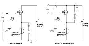
Regarding my way and the fear of input capacitance.
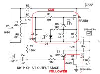
Here you can see what @Nelson Pass does with IRF610 input.
It is his classical 'Bride of Zen' circuit.
It is also a one mosfet amplifier.

Here you can see what @Nelson Pass does with IRF610 input.
It is his classical 'Bride of Zen' circuit.
It is also a one mosfet amplifier.
Okay, back to the rowing bench for me...
Thank you all!
And: I had a quick listen to my IRF610: not suitable for audio.I can still add - just heard: IRLZ24NIR, IRLZ34N, IRFZ34, IRFZ44N, IFL510VIS, UF640L-TA3, 2SK2545, STPN52K3.
I would make recommendations - IRF530 (wide, rolling), IRF820 (clean, open, elaborated, more focussed than IRF530); IRLZ24N (like "tok tok", wooden, tact, "authentic"), IRL510VIS (more focus than IRF820) - if I didn't know that every batch can sound different. Whereby 2SK2545, STPN52K3 go in the direction of BjT, but sound a little less clean in the fundamentals and deepths (compared with a TIP 31C).
Keep your hands off TO-247 types.
I know the original commenter got banned but what does the coil do?View attachment 1169746
I think this was one of Nelsons designs adopted for HP some years ago.
When I replace R3 by a CCS, I get Andrea Ciuffoli's single ended power follower - go toOne MOSFET and One resistor ...
This amplifier is for you who have a headphone: 8, 16, 32, 60 or 64 Ohm impedance.
The trafo is 2x12VAC.
The MOSFET can be any TO-220 or TO-247.
For example IRFP240, IRFP140, IRFP044, IRF540. (IRF520 and IRF610 gives a little more distortion = more MOSFET sound)
The resistor should be 5 Watt.
If you have some MOSFET laying around, this project is for you.
You get good use of your MOSFET.
I have not built it. But the SPICE test shows it is a good, solid and fun design.
It works 🙂
http://www.geocities.com/ResearchTriangle/8231/
Does anyone know if there is a reason not to use many paralleled FETs in this design to achieve less dissipation per device (and spreading the dissipation out over many heatsinks)?
Steve
Does anyone know if there is a reason not to use many paralleled FETs in this design to achieve less dissipation per device (and spreading the dissipation out over many heatsinks)?
Steve
- SteveG
- Replies: 11
- Forum: Solid State
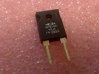
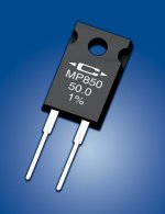
Important is R3 - best results you will get by use of a TO247 or TO220 outline from Caddock
P.S.: image 1+2 under
I want an order address for showed cinch female connectors in special outline, i. e. with additional solder lead for GND connection - go to the attachement (top view of a class-A unity gain preamp based on Andrea Ciuffoli's Power Follower).
The used cinch connectors are from WBT (early 80's) and from this company no longer available since a long time.
Thank you for advices.
Update: WBT tells me by phone, that the follow jacks are the successors:
https://wbt.de/produkte/a/detailansicht/Artikel/nextgentm-cinchbuchse-signature.html
go also to the attachments and to...
- tiefbassuebertr
- Replies: 13
- Forum: Digital Line Level
Attachments

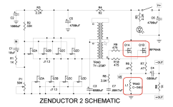
Yeah but its value is really small and its followed by a resistor
- Home
- Amplifiers
- Pass Labs
- SOMOS. Sound of One MOSFET Headphone Amp