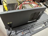
My power supply has not been able to go up to 20v since I got it, I had gotten it to go up to 14v but it does not want to go higher than that.
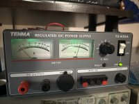
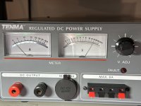
Recently it has decided it won’t go above 10v (second photo, voltage knob is turned to max)
Any ideas on how to fix it? Should I recap it?
Recently it has decided it won’t go above 10v (second photo, voltage knob is turned to max)
Any ideas on how to fix it? Should I recap it?
Attachments
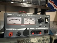
It should go up to 15 V according to https://www.manualslib.com/manual/737972/Tenma-72-630.html?page=2#manual
Does it get worse with load? What voltage is there across the ten 4700 uF electrolytic capacitors?
Does it get worse with load? What voltage is there across the ten 4700 uF electrolytic capacitors?
I have a different model, do you know if the schematics are the same?
I have the 72-630a
I don't believe it differs with load
I will take it apart and take some photos of the inside and see if those caps are in there
I have the 72-630a
I don't believe it differs with load
I will take it apart and take some photos of the inside and see if those caps are in there
You are right, I missed the A. I haven't a clue whether the schematics are the same, but I assume yours is also a series regulated lab supply with a high maximum current. If so, there should be a bank of fairly large electrolytic capacitors used for smoothing the rectified voltage.
Haven't taken it apart yet, still needed it for a quick pop up project
A load does make a difference, voltage rise on startup is slower build up, no voltage drop though, goes up to about 10-10.5v
No load it rises up to around 11v then slowly goes down to 10v with no load
I'm only able to get 13amps out of it as of right now before it taps out and cuts power for a second
I do feel the caps you describe are bad
Just to be sure: is there a switch for different mains voltages at the back and if so, is it set correctly?
If it were due to dried up smoothing capacitors, I would expect a 13 A load to have more influence than you measured. Strange...
If it were due to dried up smoothing capacitors, I would expect a 13 A load to have more influence than you measured. Strange...
No switches on the outside besides the on/off
I believe the schematics could be fairly similar to the other supply you linked above but not sure
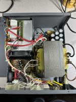
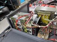
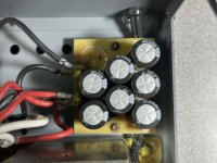
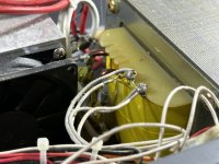
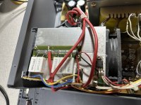
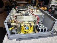
Here are some photos of the internals
I have a feeling one or few of those caps in that bank have leaked (6800uf 28v)
I believe the schematics could be fairly similar to the other supply you linked above but not sure
Here are some photos of the internals
I have a feeling one or few of those caps in that bank have leaked (6800uf 28v)
Attachments
-
 IMG_0980.jpeg501.4 KB · Views: 70
 -
 IMG_0981.jpeg617.7 KB · Views: 70
 -
 IMG_0982.jpeg476.4 KB · Views: 71
 -
 IMG_0983.jpeg446.6 KB · Views: 72
 -
 IMG_0984.jpeg421.9 KB · Views: 79
 -
 IMG_0985.jpeg400.3 KB · Views: 77
 -
 IMG_0986.jpeg456.6 KB · Views: 69
 -
 IMG_0988.jpeg485.4 KB · Views: 59
 -
 IMG_0989.jpeg429.9 KB · Views: 63
 -
 IMG_0990.jpeg525.1 KB · Views: 76
If I get new capacitors for that bank, should I add the one that is missing or just replace the current ones?
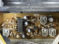
In the schematic of the Tenma 72-630 (link of post #2), there is a trimming potmeter RV1 that's used to set the maximum voltage, which is 15 V for the 72-630.
On the photos of your 72-630A of post #7, there is a trimming potmeter RV1 with a note "RV1 13 8V" right next to it. Are you absolutely sure that your supply isn't by design limited to 13.8 V maximum voltage?
As to why it sometimes only produces 10 V or so, I can't imagine it has anything to do with those smoothing capacitors. I suspect it is a rotten contact somewhere. Dirty V.ADJ potmeter maybe, or a dirty RV1? (The other trimming potmeters have nothing to do with the maximum voltage, at least not in the 72-630.)
If the problem reoccurs, you could try to clean the V.ADJ potmeter and RV1 with a mild contact cleaner. (I write a mild contact cleaner, because some are so aggressive they do more harm than good.)
Last edited:
13.8v isn’t set max, or its been messed with then, as im getting 15.05v with it now
I have deoxit D5, would that be safe to use?
I have deoxit D5, would that be safe to use?
That doesn't exactly instil confidence.I unplugged it for a day or so and its back up to 14v now
Are you judging the output voltage by measuring with a DMM or are you going by what's indicated on the moving coil meter on the supply? The meter circuit in the supply could be defective.
D5 or FaderLube would be safe to use on the trimpots. Personally I prefer Deoxit FaderLube (F5?) for pots.I have deoxit D5, would that be safe to use?
I'd measure the ripple voltage across the main capacitor bank. If it's reasonably low, especially under load, the capacitors are fine. The smaller electrolytic caps could be suspect, but unless there're signs of leakage I'd probably leave them alone for now.
If you have the service manual, I suggest giving the trimpots a squirt of Deoxit and exercising them a bit. Then recalibrate the supply.
Tom
Meter on the supply and a multimeter. The supply gauge is accurate.Are you judging the output voltage by measuring with a DMM or are you going by what's indicated on the moving coil meter on the supply? The meter circuit in the supply could be defective.
How would I measure ripple voltage on the bank? Just voltage across the red and black wire going to it with multimeter in DCV?
- Home
- General Interest
- Everything Else
- Lab Power Supply Not Getting Up To Voltage