Hello all, after lurking around for several years. I will start with my first thread.
I read a lot of composit LM3886 amps on this forum but I can not find any schematics worth of building.
I like to build a high power composit LM3886( like 6 x LM3886) amp.
On a dutch forum I found this.

Is it worth building it?

I read a lot of composit LM3886 amps on this forum but I can not find any schematics worth of building.
I like to build a high power composit LM3886( like 6 x LM3886) amp.
On a dutch forum I found this.
Is it worth building it?
Last edited:
I'm intrigued. Of course, the LME49710NA was discontinued many moons ago, but using half of an LME49720 is an easy fix for that. Just make sure to wire the other half so it doesn't chatter.
I don't see an advantage of using three LM3886es in parallel, but aside from the slightly higher cost and size I don't see any significant disadvantage either. Using three LM3886es would certainly make for a nice module for bridging should that be desired.
I've seen parallel LM3886es go into a sort of soft latch-up state if the negative supply powers up before the positive. I chose to add a little bit of circuitry to ensure that the MUTE pins are held at GND until both supplies are up. I don't know if this is an artifact of using lab supplies during testing or if it can also happen with a "real world" supply. I suspect the former.
The schematic style is the same as Elektor Electronics uses. I wonder if there's a connection there. The photography is not Elektor style. Maybe this didn't quite make it into the magazine or something. That could be a good thing.
I'm mostly intrigued by the compensation schemes in this amp. That could be worth playing with in the simulator.
I hope you go forward and build this design. I'm curious to see how it performs.
Tom

Thanks Tom for your reply. I am a great fan of your work and learned a lot about the lm3886.
It is really difficult to get proven schematics about the composit lm3886 amps.
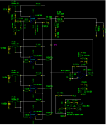
In the schematic at the right above corner is a block diagram of the bridged amp I like to build.
I will order the PCB’s ( gerber files are available)and give it a try. I still have LME49710 opamps or even try other opamps.
The origenal poster is now developing the balanced preamp, but I can not longer wait. I like to start building.
I have ordered a SMPS at audiophonics. It still needs a cage for safety.
See attachment (pdf)below.

It is really difficult to get proven schematics about the composit lm3886 amps.
In the schematic at the right above corner is a block diagram of the bridged amp I like to build.
I will order the PCB’s ( gerber files are available)and give it a try. I still have LME49710 opamps or even try other opamps.
The origenal poster is now developing the balanced preamp, but I can not longer wait. I like to start building.
I have ordered a SMPS at audiophonics. It still needs a cage for safety.
See attachment (pdf)below.
Attachments
Last edited:
Beware that that power supply often has cold solder joints on the 1/4" spades used for the output voltage. I suggest that you touch up those solder joints before using the supply.
If you want to bridge two channels of that amp to drive one speaker, you'll need the SMPS800RE. The 300RE is fine for a stereo amp (or mono block, of course).
Tom
If you want to bridge two channels of that amp to drive one speaker, you'll need the SMPS800RE. The 300RE is fine for a stereo amp (or mono block, of course).
Tom
Thanks for the hint about the spades, I will do that. And of course the power supply is to weak to get maximum power. For me it is just to prove the concept building a composit lm3886 with smps and get very low thd + n figures.
My measurement equipment(-110db)is probably the limit. ( I hope).
I also have ordered some OPA1611 on DIP adapters to test if it stays stable. But for now waiting for the PCB’s.
My measurement equipment(-110db)is probably the limit. ( I hope).
I also have ordered some OPA1611 on DIP adapters to test if it stays stable. But for now waiting for the PCB’s.
Last edited:
There are some parallel LM3886 boards on eBay. The Jeff Rowland clones look interesting. I don't see one currently, but this looks like the same idea. 180 Watts. https://www.ebay.com/itm/321292441271

On a dutch forum I found this.
The designers have gone to the trouble of reducing cross-currents in the paralleled sections through the specifying of 0.1% resistors. However it seems they've overlooked that electrolytics aren't available in such close tolerances.
C7, C13 and C21 do not appear in the parts listing but their tolerances will cause differing LF roll-off between the paralleled sections. The variation in 20Hz gain as a result of the 'lytic tolerances could lead to substantial cross-currents. I'd suggest increasing their value from 100uF to 1000uF to mitigate this. It might also be worth making them bipolars.
Asuslover the gerber is in post 3.
Abraxalito, Luckily I have ordered enough 100uF/50V electrolytics. About changing the value or type I first build it and then evaluate if it is necessary . Almost all designs I have seen have a 100uF on that position.
Olsond3, that is not a composit design with an opamp applying corrections from the feedback. The composit design has lower THD + N. There are amps from Tom(Neurochrome) and Topping with extreem low distorsion.
Attachments
Last edited:
180 W (into 4 Ω) from six LM3886 in parallel would require that you run the chips right at the absolute maximum power supply (±42 V). That's not exactly a robust design.There are some parallel LM3886 boards on eBay. The Jeff Rowland clones look interesting. I don't see one currently, but this looks like the same idea. 180 Watts.
If you allow for enough margin that you can cover ±10% variation in mains voltage, you're looking at more like 125 W (4 Ω). Three LM3886es in parallel will do that just fine. As will two of them.
In the 1970s and 80s amps were rated in "music power". It seems these days, amps are rated in "eBay power". 🙂
Tom
Is it an idea to select these capacitors with exact(0.1%) the same value?The designers have gone to the trouble of reducing cross-currents in the paralleled sections through the specifying of 0.1% resistors. However it seems they've overlooked that electrolytics aren't available in such close tolerances.
C7, C13 and C21 do not appear in the parts listing but their tolerances will cause differing LF roll-off between the paralleled sections. The variation in 20Hz gain as a result of the 'lytic tolerances could lead to substantial cross-currents. I'd suggest increasing their value from 100uF to 1000uF to mitigate this. It might also be worth making them bipolars.
It's origin is the Dutch forum zelfbouwaudio.nl
https://zelfbouwaudio.nl/forum/viewtopic.php?t=32147
It's a split off from a failed attempt to build to a 6 X LM3886 /channel amplifier, and according message nine in that thread it's designed by ChatGPT 4.
https://zelfbouwaudio.nl/forum/viewtopic.php?t=32147
It's a split off from a failed attempt to build to a 6 X LM3886 /channel amplifier, and according message nine in that thread it's designed by ChatGPT 4.
Last edited:
Is it an idea to select these capacitors with exact(0.1%) the same value?
That would be meaningless for electrolytic capacitors. They are crude and short lived parts.
At full ratings, typical ones are only rated to meet specs for 1000 hours of operation.
They must be considerably derated to have a useful lifetime.
Thanks Rayma for your reply.
Tom, If I may ask, how did you do the decoupling of the negative input of the lm3886?
In his first attempt he build a gigant oscillator.
Then the second design worked with one, two or three lm3886’s.
Next he will test the balanced preamp witch also is fit for unbalanced duty.
Because I was long time searching for a 6 x lm3886 composite amp schematic I no longer wait and also start building it.
Hopefully with a little support from the experts here and from the dutch forum I can complete it and share it with the DIY community.
^^ Yes, but why did you not provide the mentioned information?
And is your intended use of the amp to be, related to this business? http://monstercore.nl/
An amplifier intended to be used for PA, clubs, party's and garden party's will require a different design focus as one intended for domestic HiFi.
And is your intended use of the amp to be, related to this business? http://monstercore.nl/
An amplifier intended to be used for PA, clubs, party's and garden party's will require a different design focus as one intended for domestic HiFi.
I think it is not relevant to share more info because there is no more then a schematic( and a confirm that it works).
My goal should be clear, build a bridged composite LM3886. Because I have already a lot of experience with other designs.
And my main hobby is to build projects and not so much use them.
In my business the LM3886 has no place, there we need light and powerfull amps( several Kw). DIY is there a no go. People like only to rent known brands.
At home I a have a studio and dedicated listen room thats were I intend to use/test this amp.
It has to compete with hypex, purifi and tube amps.
Ordered the PCB's with a express service, if I am lucky they will arrive before friday.
In a parallel amp you want as low DC gain as you can get. So I'd go with the schematic shown in Post 1.Tom, If I may ask, how did you do the decoupling of the negative input of the lm3886?
Was the phase noise any good? 🤣In his first attempt he build a gigant oscillator.
That's a pretty common outcome. Thoroughly test the amp both with sine waves and square waves. Drive it to clipping and make sure that it recovers.
Tom
Tom, I will do that. After I have a bigger power supply and bigger dummyload.
Probably I start with the 2 x lm3886 and 20x gain, unbalanced, because I have ordered the 300W smps and have a 100W dummyload.
Probably I start with the 2 x lm3886 and 20x gain, unbalanced, because I have ordered the 300W smps and have a 100W dummyload.
This scheme of mine (even without trimmer offset setting) works perfectly.
Batteries are added to simulate the natural offset of the 3886.
2K multi-turn trimmers can be added to equalize the offset on each chip... theoretically... And maybe just one trimmer is enough.
All Mute pins are connected together with a 3300uF/50V + 2200 ohm/2W RC delay network and no Bump is heard.
Attachments
Last edited:
- Home
- Amplifiers
- Chip Amps
- Schematic worth to build it?