I did see those but was hoping to find a screw mount version.
If I went this route, could 8 of these work? 4 per channel?
https://www.mouser.com/ProductDetai.../VS-HFA30PB120-N3?qs=eyrSuY1LhL1uIclI1A/5jA==
I would need to fix them to a bread board or find a prefabricated board to add them to with heat sinks.
If I went this route, could 8 of these work? 4 per channel?
https://www.mouser.com/ProductDetai.../VS-HFA30PB120-N3?qs=eyrSuY1LhL1uIclI1A/5jA==
I would need to fix them to a bread board or find a prefabricated board to add them to with heat sinks.
Attachments
@Bensen i think I’m going to bite the bullet and just get those two IXYS. Since the power supply is the hardest component to take out I’m going to do it right the first time.
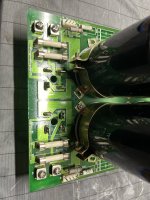
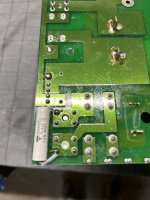
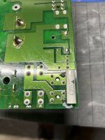
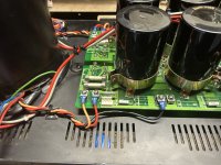
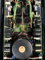
Here is a pic of the two Roederstein soldered under the board across T1 and T2 secondaries.
I also pulled out the screw mount diode bridges and installed spade connectors so I can go to the rectifiers and back to the boards.
Here is a pic of the two Roederstein soldered under the board across T1 and T2 secondaries.
I also pulled out the screw mount diode bridges and installed spade connectors so I can go to the rectifiers and back to the boards.
Attachments

I have a couple questions I could use some help answering.
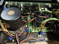
1. When checking the polarity of the AC, can it be done without the amp boards installed and only the PSU hooked up? I have two more parts I am waiting to arrive so won’t have the amp boards done until probably this weekend.
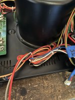
2. I noticed the Primary and secondary transformer wires were not cut to the exact length and instead the excess wire zip tied together. Is there a reason it was done this way? I’ve always thought AC wires should be cut as short as possible and twisted…
1. When checking the polarity of the AC, can it be done without the amp boards installed and only the PSU hooked up? I have two more parts I am waiting to arrive so won’t have the amp boards done until probably this weekend.
2. I noticed the Primary and secondary transformer wires were not cut to the exact length and instead the excess wire zip tied together. Is there a reason it was done this way? I’ve always thought AC wires should be cut as short as possible and twisted…
Attachments
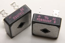
Of course right after I ordered the IXYS diode bridges, I get an email from Diotec with details on purchasing their FDB3506P/T that fits the PSU board.
They had a deal in place for purchasing more, so I went ahead and purchased 12 pieces from them. I will post some kits for anyone interested in modifying their HCA-3500.
I will see if Mouser will take back the diodes I purchased from them.
Any help on the above questions I asked about the AC Polarity and the transformer wires being shortened?
Maybe to make repair easier or just out of lazyness. I would cut them to a comfortable length.2. I noticed the Primary and secondary transformer wires were not cut to the exact length and instead the excess wire zip tied together. Is there a reason it was done this way? I’ve always thought AC wires should be cut as short as possible and twisted…
Yes. All the email communication was about the soft recovery model. We even spoke over the phone and Joe was a very nice guy.
Right now the only two parts I’m waiting on are the diodes and the PR9372 2.2k resistors from Parts Connexion.
I’m keeping the opposite channel at stock so I can reference it if I have any issues with the channel I rebuilt. Once I confirm the rebuilt channel is playing and bias is stable I will work on the other side.
Working on AC polarity will be last unless I can do it without the amp boards attached.
And I’m still on the fence about keeping or removing the Dynamic Bias feature. If I remove those two resistors, I would defeat TVR3 and just need to increase TVR1 to 20mv, correct?
Removing R94 (100k) will cut audio signal to dynamic bias input. Removing R140 (10k) will isolate TVR3 and Q35 optoisolator out of circuit.
Slightly adjust TVR2 if TVR1 will not give sufficient range to reach ~20mV (+/-2mV).
After you complete your mods, be sure to double check all parts and connection points, then power up the upgraded channel slowly with a variac and monitor current draw. Watch bias with a dvm and make sure to not exceed +50% of high bias (20mV). At continuous high bias, the amp will run quite hot so do not place it in an enclosed rack without plenty of forced-air cooling.
20mV is 20 mV, logically.
How about the DC servo ? The feedback shunt 1k8 is parallel to the 33k that goes to the output = virtual ground of the famous opamp.
How about the DC servo ? The feedback shunt 1k8 is parallel to the 33k that goes to the output = virtual ground of the famous opamp.
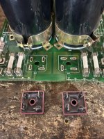
Diotec bridges arrived Saturday and they are, indeed, the soft recovery. I got them installed, shortened my secondary wires, and hooked the psu back up. Confirmed it was all good on voltages for both B+ and B- on both sides.
The PR9372 2.2k resistors aren’t set to arrive until Tuesday but I popped in a couple Dale RN55 resistors I had on hand and fired up the first channel on the variac. No problems or smoke so ran the unit and set the bias. I ended up leaving the dynamic bias resistors in but may remove them later by just snipping the two out.
I was able to finish the other amp board but need to clean it all up and buy some more thermal paste before installing it back.
Been a pretty easy recap with all of @bigskyaudio’s notes. I’m going to have some spare Holco resistors, PR9372 resistors, Diotec bridges and some Vishay Roederstein capacitors I’m going to sell as kits for anyone wanting to complete these mods.
The last thing I’m going to do is the AC polarity once I confirm everything works.
Attachments
I installed the completed right channel last night and it fired up with zero hiccups. The bias was off quite a bit from before but I adjusted it again and it was stable on my work bench. Those pots are touchy so I may have bumped it while working on it.
The last thing for me to do was check polarity so I found a 2 prong power cable that allowed me to turn it either way. Took me a bit to realize how to do it correctly, but I put the black probe on the safety ground lug coming off both the IEC earth inlets. I then connected the red probe to bare metal where an empty screw hole was. I couldn't get a reading on my first DMM so I switched to another and was able to get readings of 0.028VAC in reverse on the left channel, so that channel was good on polarity when hooked up correctly.
The right channel, however, showed 0.031VAC when plugged in at the normal polarity. I haven't made a switch yet but from what I understand I just need to swap the gray (coming off fuse) and red (coming off N on IEC) wires labelled IN.
After that I should be done with the amp except for some more biasing and listening but I plan to do that in my main audio room. The only thing I did not complete on @bigskyaudio's list is to remove the dynamic bias feature. Could anyone explain a benefit to removing it? I know if it is removed the amp will always be running at the full 20mv bias and warm at all times. If I leave it in it allows for the amp to "idle" at lower temperatures and wattage.
Amp is all done and now in my listening room. I’m going to check bias one more time in that room and not my hot garage. Heaving that thing up the stairs was tough! I see why @bigskyaudio decided to not mod them anymore.
I hooked it up this morning and gave it a quick listen on my Magnepan LRS+ just to make sure it was playing and there was no noise. All checked out and music played.
Still hoping to get some feedback on the dynamic bias feature and if anyone thinks a 20 amp breaker is absolutely necessary with this amp. I read a lot of forums with people mentioning a dedicated breaker.
Attachments
I am in the process of restoring an HCA-3500 right now, doing my research and seeing what parts I need to gather. How has this restoration turned out for you and do you have any of the FDB3506P/T-S diodes or Holco H4 feedback resistors left to sell? The Big Sky mod sure cleans up the amp boards a lot with removing all of those bypass caps, very good work you did! Interested to hear the results and any advice.Of course right after I ordered the IXYS diode bridges, I get an email from Diotec with details on purchasing their FDB3506P/T that fits the PSU board.
They had a deal in place for purchasing more, so I went ahead and purchased 12 pieces from them. I will post some kits for anyone interested in modifying their HCA-3500.
From Stereophile......
Still hoping to get some feedback on the dynamic bias feature and if anyone thinks a 20 amp breaker is absolutely necessary with this amp. I read a lot of forums with people mentioning a dedicated breaker.
https://www.stereophile.com/solidpoweramps/100parasound/index.html
Proprietary Music Activated Bias circuitry enables full bias only when music is playing. After music has stopped playing for about a minute, bias is reduced to a trickle, thus minimizing power consumption and heat.
From the specs https://parasound.com/products/vint...WnSw4XaDbAXI5ylNpx38xo0icq0X_ZlvJcI1vjjHBdAcQ
120 amperes peak per channel
...
100 lbs, 22 inches deep. It's a monster.
I didn’t end up using the unit much after finishing it. My friend has it on his Magnepan 1.6 (I think) and he loves it. He also has a 20 amp breaker.
i thought my F4 monoblocks with BA3B as a front end sounded a bit more detailed and they fit on my rack better.
However he loves it and has a Threshold 4000a I also sold him and he likes the Parasound more.
As for restoring it. It was really easy but take tons of pictures and take your time. I would start with the psu test it to ensure it works then do one channel at a time.

- Home
- Amplifiers
- Solid State
- Parasound HCA-3500 Modification Thread