Hi
Here I am again with a new project.
This time I bought a radio from the 50s, the Ever Ready Super King.
These battery powered radios usef powered a 90V battery.
I will use either 10 9v batteries or some li-ion cells and a boost instead. Using a boost will allow the batteries to be recharged.
The filaments’ current is 25mA or 50mA at 1.5V.
I will try to re-use as many parts as possible.
As this is a single ended amp, the schematic should similar to the fender champ.
I will be posting as I move along.
Cheers
Pedro
Attachments
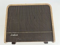
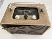

Ever Ready Super King
You've made a little mistake there, Pedro. It's not a "Super King", but is a "Sky King" as is clearly shown in one of your images.
For reference, the "Sky King" schematic is included in this article: https://www.radiomuseum.co.uk/Sky King.html
P.S. There's an interesting history of Ever Ready radios on this (safe) site:
http://historywebsite.co.uk/Museum/Engineering/Electronics/EverReady/EverReady.htm

They are
V1 - DK96
V2 - DF96
V3 - DAF96
V4 - DL96
I will use V4 as it is, as the output tube.
The others, I will have to think which ones I am going to use and the stage where makes sense to put them.
V1 - DK96
V2 - DF96
V3 - DAF96
V4 - DL96
I will use V4 as it is, as the output tube.
The others, I will have to think which ones I am going to use and the stage where makes sense to put them.
I am not familiar with those tube types so can't comment. Big thing to be careful of is electric shock. It that set does not have a power transformer, then use an isolation transformer for the power to it.
According to the circuit description in the article:
V1 is a heptode valve operating as frequency changer.
V2 is an RF pentode operating as intermediate frequency amplifier.
V3 is a diode pentode valve.
V4 is a pentode output valve.
Possibly input the guitar across pot R8 after isolating it from the junction of R7 and C21 as well as breaking the connection to the diode section of V3?
I was thinking of desoldering everything, wire the valves on the preamp as triodes and keep the output stage as it is.
Hi guys,
I need some help with these valves.
1- As these valves are pentodes and one heptode (which I won't use), I don't know if it is a good idea to use them as pentodes in the pre-amp stage or
connect them in triode mode (just for the pre-amp), since pentodes/tetrodes are, most of the time, used in the power-amp section.
Even VOX abandoned the idea of a pentode in the input of the pre-amp.
2 - The data sheets only have pentode curves, which I don't know how to convert into triode curves. Any ideas?
3 - These valves have a direct dc heater, which I don't know how to bias. These heaters take around 1.5V and if I need, let's say, a Vgk of -3V what can I do? Do I have to apply -1.5V directly on the grid? Do you think it would work to have a resistor in series with the heater and apply a higher voltage on the other end, while keeping the grid at 0V? In the Sky King all valves have their heaters connected to a 1.5V battery, which means that it will be always using the -1.5V grid curve. At least for the output pentode, I wanted to lower the grid voltage more.
Cheers,
Pedro
These 60s radios have nice boxes for conversions to guitar amps. I was hunting some of them myself.
Check this video, where someone built something like you are trying with similar tubes:
And schematic:
https://www.hoofbags.me.uk/geekiestuff.html
2. Check if there are any spice models for these tubes. There you could easily simulate the triode operation and plot the triode lines.
3. Are you using batteries, transformers or how are you going to power the amplifier?
You can easily use batteries for grid leak biasing. The current is really low, and one cell will last a long time.
The loadlines normally consider the cathode voltage at the negative side of the heater. So you can either use a separate battery for the heaters or, if you want to use a power supply:
Check how I did it here using a single 9V supply:
https://www.instructables.com/High-Gain-Subminiature-Amplifier/
I used different tubes, though.
Here: https://www.instructables.com/Push-pull-Tube-Amplifier-Using-Subminiature-Tubes-/,
where I use LiPo batteries, the ICL7660 was used to get the negative voltages for the bias.
Check this video, where someone built something like you are trying with similar tubes:
https://www.hoofbags.me.uk/geekiestuff.html
2. Check if there are any spice models for these tubes. There you could easily simulate the triode operation and plot the triode lines.
3. Are you using batteries, transformers or how are you going to power the amplifier?
You can easily use batteries for grid leak biasing. The current is really low, and one cell will last a long time.
The loadlines normally consider the cathode voltage at the negative side of the heater. So you can either use a separate battery for the heaters or, if you want to use a power supply:
- Elevate them with resistors in series, so that the cathode is at a higher voltage than the grid.
- Use grid leak bias with negative voltages.
Check how I did it here using a single 9V supply:
https://www.instructables.com/High-Gain-Subminiature-Amplifier/
I used different tubes, though.
Here: https://www.instructables.com/Push-pull-Tube-Amplifier-Using-Subminiature-Tubes-/,
where I use LiPo batteries, the ICL7660 was used to get the negative voltages for the bias.
@Thomasha
Hi Thomas,
I saw the video and it is nice, thank you for that.
2. Regarding the spice models, the user Sorento replied to me ,in the models' thread some days ago, and posted all of them.
3. I am planning to power the amplifier with 6 Li Ion batteries from a laptop battery, and use a boost to 90V. Regarding the heaters I am not shure if I am going to use 4 type C batteries in parallel (that I already have) or use a tap from one Li-Ion cell and then use a buck converter to 1.5V. To be honest I am not sure about this one, since it will add noise to the heater. I liked the idea of tapping the Li-ion cells, since when charging, you would be charging the batteries to both the heaters and to the rest of the circuit and not to check if the levels of the 1.5V batteries is still ok.
Another option, according to what you said, would be to elevate the f+ to, for example, 4.5V with 3 batteries in series anf connected f- to a resistor to give 3V. I like this idea. I think I will use this one.
Kind regards,
Pedro
Though I'm not sure where these tubes once were designed, there are JEDEC equivalents as well, of course:They are
V1 - DK96
V2 - DF96
V3 - DAF96
V4 - DL96
DK96 = 1AB6
DF96 = 1AJ4
DAF96 = 1AH5
DL96 = 3C4.
Due to the poor voltage gain of those low power battery tubes, I'd recommend to use the small signal pentodes as such.
Best regards!
Hi Guys,
From what I've seen, the heater has two pins (f+ and f-). Apparently f- is/acts like the cathode. Does this mean that if I want a Vgk of -1.5V, I will have to apply +1.5V to f- and ground f+ ?
Cheers,
Pedro
From what I've seen, the heater has two pins (f+ and f-). Apparently f- is/acts like the cathode. Does this mean that if I want a Vgk of -1.5V, I will have to apply +1.5V to f- and ground f+ ?
Cheers,
Pedro
No, the voltage should be higher at f+ than at f-, otherwise it will not work.
It is a direct heated cathode, the heater is the cathode.
You either elevate everything, like using a different battery (check out A+, B+ and C+ batteries in old schematics).
If you want Vgk of - 1.5V, you need to elevate f- to 1.5V and f+ to 2.75V (1.5V+1.25V, with 1.25V the heater voltage drop).
Or you play with some grid bias, by applying -1.5V to the grid.
In my schematic I had all heaters in series, so that the cathodes of the following stages are elevated, and you can actually bias the grid using positive voltages.
In the second amplifier I used the ICL7660S to invert the voltage and supply negative voltages to the grids.
Keep in mind that those tubes also conduct a bit on the positive side, if I am not mistaken. So even if the f- is at 0V there will be some current flowing.
Old Schematics also use very high grid leak resistors (>2M), which somehow result in small negative voltages at the grids. (Check the supro super)
Thanks Thomas. I was being stupid.
I don't know if I am right, but wouldn't wiring the heaters in series give cathode voltages of 4.5V, 3V, 1.5V and 0V, so each valve would see a different cathode voltage?
I don't know if I am right, but wouldn't wiring the heaters in series give cathode voltages of 4.5V, 3V, 1.5V and 0V, so each valve would see a different cathode voltage?
You need to return the grid leak resistors to the negative filament ends of each related tube then.
Indeed, series heating is more than tricky with directly heated tubes.
Best regards!
Indeed, series heating is more than tricky with directly heated tubes.
Best regards!
Thanks Kay.
They are really tricky ! As I have many 7806, I will use one to output 2 different voltages to apply to f+ and connect one resistor to f- and adjust it according to the voltage I want. This should work.
By the end all of them will have 1.5V in the cathode, except for the power one, which I want it to have 3V.
Kind regards,
Pedro
I tried putting together a circuit in LTSPICE. What do you think? The input is a 144mV sine wave. R13, in the real application, will have a 10k pot in series.
The transformer is 18kohm:2ohm and I've increased the voltage from 90V to 130V (I am going out of the spec max values). Even with this voltage, I cannot get more than 90mW! Maybe it will be ok for bedroom playing though ...


The transformer is 18kohm:2ohm and I've increased the voltage from 90V to 130V (I am going out of the spec max values). Even with this voltage, I cannot get more than 90mW! Maybe it will be ok for bedroom playing though ...
Sounds OK, I couldn't get much more than 65 mW from the 5672 in SE.
Not sure if the setup of the simulation is close to what you are trying.
Cathode biased tubes have some play due to the cathode resistor.
With these tubes the bias is basically fixed, not sure how differently both circuits will behave when simulated.
Another point is, are you checking the load lines for these tubes? Is 100k still OK? I thought these tubes used lower anode resistors, more like 20k or 47k to keep a minimum current flowing.
Thanks for the reply.
I used that value, since the sky king uses 1Mohm of anode load (post #2 has a link to an article with the schematic). So, I tried a large value to maximize gain as much as possible.
But yes I will have to check the curves.
I was not planning to, but I am thinking of adding the valve I left of, the heptode. I will re-wire it as a pentode to increase the gain a bit.
However, I am not expecting much, since the output stage is already saturated.
Cheers,
Pedro
- Home
- Live Sound
- Instruments and Amps
- Valve/tube radio to guitar amplifier