Eh that is what Tombo56 designed. 10A even.
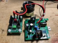
My version is a potpourri to make it suitable as PSU. The modular approach is exactly what I detest as it serves no real purpose and leads to wiring and messy setups like this one. Could all have been on 1 board with just AC in and DC out connectors when used for a simple class D amplifier. That is my next project.
My version is a potpourri to make it suitable as PSU. The modular approach is exactly what I detest as it serves no real purpose and leads to wiring and messy setups like this one. Could all have been on 1 board with just AC in and DC out connectors when used for a simple class D amplifier. That is my next project.
Attachments
Last edited:
Understandable for anyone with higher standards than myself. Newer codecs like aptX Adaptive and LDAC exceed the quality of my source material, so I appreciate the convenience of using BT.
A wire seems about the highest possible standard to anyone 🙂
That recent codecs may be superior to the old ones as found on that board, they do not outperform a wire. The convenience is paid for with lossy compression, encoding/decoding, latency, phone dependance and RF straying in the audio chain for free 😀
That recent codecs may be superior to the old ones as found on that board, they do not outperform a wire. The convenience is paid for with lossy compression, encoding/decoding, latency, phone dependance and RF straying in the audio chain for free 😀
Last edited:
This is art ))A wire seems about the highest standard possible to anyone 🙂

All is fine. I have to bother as having clean PSUs is quite hard. As high quality is the motivation to do anything in audio it contradicts to choose anything radiating RF. A feeling coming back everytime I pick up the smart phone that is forced upon me as remote control 🙂
Tried LDAC and it performs fine. The best is the “disabled” setting though as thankfully the radio is then switched off in this one.
Tried LDAC and it performs fine. The best is the “disabled” setting though as thankfully the radio is then switched off in this one.
I appreciate people that appreciate the finer details. Maybe I'm too uncultured, or brain damaged. 😆
Guys, after warming for two weeks I am shocked with sound. This is absolutely another incredible level of sound and scene. I advise all owners of class D amplifiers to try to make a similar power supply.Made a final one (well, a few) but haven’t tried this particular one yet. Based on a 5.6A toroid, a LT4320 rectifier, 15000 uF cap and LT1084. The test version was already better than the switcher.
Toroid + "ideal diode bridge" (you can use many variants). In rectifier I leave chinese cap JCCON (tried few variants of "audio" caps here but this cap is better for me) and after LT I use Panasonic FR. Remember, few weeks
I didn't follow everything, are you using a linear power supply with this card?I am shocked with sound
I use DIY linear power supply with Topping Pa3s on two MA12070s. Also added LT3045 5v for AVDD rail of MA chips
I really like balanced so I tried this yesterday. A little disapointed that the noise was just the same as single ended through the tone controls.If you want the full potential of this board, remove the SMS capacitors, just before the chip....Read RADIAN's posts !!!
And the same as when negative part of the signal was muted and positive doubled.
Did you solder your connections on the smd pads as close as possible to the chip?
Be careful... On this card the in - signal is connected to ground.
Look carefully at your soldering!
If in doubt, you can remove the smd grounding resistor, right next to in-
Be careful... On this card the in - signal is connected to ground.
Look carefully at your soldering!
If in doubt, you can remove the smd grounding resistor, right next to in-
So after an year with TPA3255 at LF and Topping Pa3s at HF Im still happy.
Also O-NOORUS OA36S is an very good amp, only higher DC offset if it's important.
Pa3s about 4 mV and O-NOORUS 19mV but they sound pretty much the same so, an cheaper good buy.
https://www.o-noorus.com/products/oa36s-dual-ma12070x2
https://www.audiosciencereview.com/...dio-tpa3255-260-2-29a-amplifier-review.50208/
All balanced, MA12070 filterless like that.
Very good mariage with TPA 3255 at LF which are a bit narrower than the wider MA12070 at HF.
And it's very quiet, nearly no noise.
I would be lying if I say its dead quiet, but I have to put my ear realy toutching my wave guide tweeter.
But at least 50% of my sound is measuring your listening point.
https://www.audiosciencereview.com/...phone-method-mmm-for-dummies-using-rew.51333/
Gain staging outputs, I run two way active and trim EQ left and right to the room.
Thats the new school that you all should do.
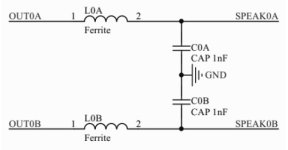
That measured higher DC offset may be due to RF content because of being unfiltered. Together with the speaker wiring this will lead to radiated RF in the 30 MHz to 1 GHz region. That is why output filtering is both an essential selection criterium and a minimum requirement.
https://www.infineon.com/dgdl/Infin...N.pdf?fileId=5546d46264a8de7e0164b359d78016f6
https://www.infineon.com/dgdl/Infin...N.pdf?fileId=5546d46264a8de7e0164b359d78016f6
Last edited:
Yes, removed the input caps and soldered at chip side as in post 1730. Only connected + and - of balanced signal. Not ground.Did you solder your connections on the smd pads as close as possible to the chip?
Be careful... On this card the in - signal is connected to ground.
Look carefully at your soldering!
If in doubt, you can remove the smd grounding resistor, right next to in-
Tanks for the warning
Update, it is better with Mundorf cap in rectifier 👍Toroid + "ideal diode bridge" (you can use many variants). In rectifier I leave chinese cap JCCON (tried few variants of "audio" caps here but this cap is better for me) and after LT I use Panasonic FR
LDAC from my Android Phone to my SMSL DL200 DAC sounds better than feeding the same via USB from my Laptop.I appreciate people that appreciate the finer details. Maybe I'm too uncultured, or brain damaged. 😆
It don't mean that it will be better than dedicated maxed out USB solutions but it certainly sounds really good.
- Home
- Amplifiers
- Class D
- Infineon MA12070 Class D