I have 2 M2 clones built with Tea Bags boards. I connected the first M2 I built which had been sitting unpowered for about one year and noticed a greatly diminished output from the left channel. Both Q1 and Q2 are heating up but I did notice that Q1 is running about 10F lower in temperature than the right channel which produces the correct output. I poked around on the board looking for a bad solder joint with no luck. I replaced the problem M2 with a second M2 and confirmed the issue is isolated to the left channel board. Power supply voltages are fine. The only thing that changed was I did remove the fender washers compressing Q1 and Q2 to verify the FETs make and model. Is it possible I damaged one of the FETs doing this? Any help isolating the problem is appreciated. Both of my amps have operated flawlessly since I built a few years ago.
Jim
Jim
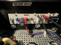
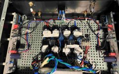
I have an overhead pic of the amp but the system will not me upload - too big even though it's only 600 kB
One shot in the dark.....I see your optocouplers have sockets.....so they are easy to change!

Did you measure anything, for example voltage over the source resistor of the bad channel!
so less shots in the dark!
:--))
so less shots in the dark!
:--))
I have not but I will. Actually the amp performed flawlessly so I never had to troubleshoot. What voltages would be helpful to measure other than the source resistor? I guess this should have been my original question.
This may be the issue. I took 3 measurements and the winding between pins 2 and 3 are different on the problem channel. Measurements below.Were they working properly before they sat around for a year? I once had a bad Edcor input transformer that created low output. Check all readings on the pins of the Edcor transformer carefully. Good versus questionable channel.
Pins on new unused Edcor iron:
1-3 45 ohms
1-2 20 ohms
2-3 24 ohms
Pins on good channel (right) climbs to approximately same values as new Edcor
Pins on problem channel (left):
1-3 95 ohms
1-2 20 ohms
2-3 110 ohms
Other side of Edcor transformer pins 5,6,7 measure about the same for all 3 cases.
Now to see if I can unsolder the 8 pins to save the board and parts!
I also measured the voltage drop across R13 and R14. Both channels measured about 400 mV and voltages across R3 and R4 measured about 200 mV on both channels with 10k resistor on input and dummy load on outputs.
Advice?
Thanks for that advice sir. I put a 500 mV of a 1Khz sine wave signal on the input and got these results:
Right channel - good one
Output of auto-former (PIN 7) 2.63 Vac
Amp output - 2.49 Vac
Left channel - problem
Output of auto-former 239 mV AC
Amp output - 226 mV AC
I checked to make sure that I got the same voltage on the problem board at the input node and PIN 1 to make sure it's not a wire or solder joint issue.
So I'm getting the expected 5:1 step-up in voltage on the good auto-former but not on the problem channel. Looks like emuffler was correct!
please, go back and measure what you didn't and what I asked for - output of JFet buffer, so we'll know what exactly is on input of Edcor
just bad channel, we know for good one
just bad channel, we know for good one
I'm sorry but that measurement was the same on both channels and very close to the input voltage, so I did not report. (I measured at pin 1 of the auto-former which looks like the output of the buffer.) The difference was the ouput voltage of the auto-former.
Anyway, my amp is fixed. Took me an hour to replace the bad Edcor auto-former. The amp is sounding glorious once again!
Thank you for your help Zen Mod.
Jim
Anyway, my amp is fixed. Took me an hour to replace the bad Edcor auto-former. The amp is sounding glorious once again!
Thank you for your help Zen Mod.
Jim

Now that you've removed the faulty Edcor, do you see any obvious damage (eg. broken wire)?
Anyway, congratulations on your M2 repair.
Anyway, congratulations on your M2 repair.
I did at the time and I have no doubt it was somehow self inflicted! Very fine wire coming from the core to the pins!


Unfortunately, the auto-former took a beating removing so measurements after removal were meaningless. I do know that the primary winding on the bad channel measured about 2 times the correct resistance when tested on the board. I guess that explains why I could still hear music from the bad channel. I was not getting any voltage gain. Those Edcor's do look fragile with very small wire. It would be nice if they were mounted remotely.Now that you've removed the faulty Edcor, do you see any obvious damage (eg. broken wire)?
Thank you. Those wires do look quite fragile.
Glad you guys were able to remove and replace the Edcors. That must have been a lot of work.
Glad you guys were able to remove and replace the Edcors. That must have been a lot of work.
- Home
- Amplifiers
- Pass Labs
- Help troubleshooting M2 clone