Dear forum,
It is not a new idea, but everywhere where I saw something like this in the internet, it was never accomplished and the thread just ended up with no conclusion.
I want to raise a topic of a Guitar pickup system, where it is possible to connect them in any possible way (parallel, series, out of phase) with the help of a microcontroller onboard. This was done ones commercially by a Music Man company in their Reflex Game Changer guitar. I was thinking on what it takes to re-make something similar.
QUESTIONS
- As the guitar pickup output has high impedance, and in general guitar output has a high impedance, when wired canonically of course, I am very concerned about preserving this high impedance (if it is at all possible). As I understood, the analog switch, even with the lowest on-resistance will affect the output of the pickup and lower the output impedance.
Q1: is it indeed like that and it is not possible to carefully select such components, so the original impedance of the pickups is preserved?
Therefore, I see recommendations to use a buffer, e.g. op-amp, between the pickup and the switch, so the sound characteristics are preserved, but the signal is then "transformed" into a low-impedance environment. As I understand, this is a compromise to use digitally controlled switches. Moreover, some people prefer the guitar to output a low-impedance signal, as it eliminates a lot of problems with long cables, nasty guitar pedals, etc. In other words, there's an opinion, that low impedance is not bad at all.
Q2: if the buffer is needed, is it enough to put it after the pickup before the first switch for every pickup? Or does this chain needs more buffers? - Buffer: I know there are a lot of buffer options with JFET and other transistors. I think the choice here is: as smaller as possible, as less components as possible, the best sound preservation. For me it looks like Op-Amp is the option to go, even if it can be costly.
Q4: what do you think?
Last edited:
Ojee, I made such switching setups in the mid seventies. To make the story short: most of the sounds were horrible and not to the taste of the musicians. Besides that, I see you're planning to use a matrix. Very good at what you're trying to build. But; how do you want to control all these different connections? And not only that: how do you think to switch from one connection to the other in a very quick way during playing?
Hm, get some info from professional guitar players and then start your project. Good luck any way...
Hm, get some info from professional guitar players and then start your project. Good luck any way...
In that era I made similar experiments with my guitar wiring.
At the end the plethora of switch combinations will end disappointing,
as the real character of sound does not change that much.
Imho they are only a small part of the sound puzzle -
the biggest part is in your fingers.
And on stage I want to focus on playing, not fiddling with complicated switch settings.
Thus my setup is as simple as possible.
just my 2c

100% this.And on stage I want to focus on playing, not fiddling with complicated switch settings.
Thus my setup is as simple as possible.
just my 2c
Even push-pull pots can be an embuggerance if you need to change pickup positions and amp/fx patches in a hurry.
And yeah.... I've played with wiring and pickup.configurations in the past. As was said, I also found most to be disappointing or just unusable.
But to the OP: hey, .it's all good! And if you go ahead: good luck, and I hope you find something that augments your playing and tone. If it works for you and your music, then that's fabulous. 😁
Cheers, and regards,
Ant
Hey, guys! Thanks for the attention.
Microcontroller will get the data from the application via USB or Bluetooth. It shouldn't be a problem for me to draft a desktop/mobile or web application for this, since that's my daily bread. I have an experience with microcontrollers as well, and see some new cool ones available today, the size of a penny and capable of doing really great things. So, no plethora of switches on the guitar, no. Just a five-way regular switch, which will scroll through 5 slots of memory (I still need to work this out, maybe that should be a digital one), and of course you can push a preset from the application into the memory as well.
It all started with me discovering some Stratocaster guitars built by Ibanez and other manufacturers which had more than 5 positions, like additional switch which puts the 5-way-switch into 4-5 other alternate pickup wirings. Therefore, I decided, that I don't want to be limited in selecting the pickups I want to engage. Especially, that I do this for finding a specific studio sound, not the stage sound. Which means I have a time to carefully play around with different configurations in the app, upload it to the guitar, record a piece of music and forget about it. After all, even if I end up with using just those famous 5 wirings, that will be a great project to accomplish, as well, as the wiring will become more visually evident to me, understanding the difference of serial and parallel sound differences, etc.
I have a Music Man Reflex Game Changer Bass guitar, and I am very happy with it. It has two humbuckers, but actually, those are 4 coils, which I can interconnect in a described manner as I want. I was able to find several interesting sounds, which are far from any wiring available on factory Music Man basses. I looked under the hood and the PCB is not that big. I can't recognize all the components there, since they are covered with some mat black "gum-paint", not sure why, but I believe it is very close to something I modeled in my diagram.
After all, if we move away from the fact, that all 3 pickups in series may sound awful 😆, I really want to focus on those questions about the choice of components and overall, on a possibility to preserve a good robust guitar pickup sound when they are beyond all the switches and matrices. And of course, the buffer is still quite a mystery to me, in terms, that I understand why it is needed, but not sure, how many of them.
But; how do you want to control all these different connections? And not only that: how do you think to switch from one connection to the other in a very quick way during playing?
Not going to invent a wheel here and going to follow the Music Man approach:At the end the plethora of switch combinations will end disappointing,
Microcontroller will get the data from the application via USB or Bluetooth. It shouldn't be a problem for me to draft a desktop/mobile or web application for this, since that's my daily bread. I have an experience with microcontrollers as well, and see some new cool ones available today, the size of a penny and capable of doing really great things. So, no plethora of switches on the guitar, no. Just a five-way regular switch, which will scroll through 5 slots of memory (I still need to work this out, maybe that should be a digital one), and of course you can push a preset from the application into the memory as well.
get some info from professional guitar players and then start your project.
That's true. I am a guitarist myself, as well as I can call myself a multi-instrumentalist, since I do play several other instruments.the biggest part is in your fingers.
I've been playing on stage for long time, but now I really want to focus on my home-studio gear.And on stage I want to focus on playing, not fiddling with complicated switch settings.
It all started with me discovering some Stratocaster guitars built by Ibanez and other manufacturers which had more than 5 positions, like additional switch which puts the 5-way-switch into 4-5 other alternate pickup wirings. Therefore, I decided, that I don't want to be limited in selecting the pickups I want to engage. Especially, that I do this for finding a specific studio sound, not the stage sound. Which means I have a time to carefully play around with different configurations in the app, upload it to the guitar, record a piece of music and forget about it. After all, even if I end up with using just those famous 5 wirings, that will be a great project to accomplish, as well, as the wiring will become more visually evident to me, understanding the difference of serial and parallel sound differences, etc.
I have a Music Man Reflex Game Changer Bass guitar, and I am very happy with it. It has two humbuckers, but actually, those are 4 coils, which I can interconnect in a described manner as I want. I was able to find several interesting sounds, which are far from any wiring available on factory Music Man basses. I looked under the hood and the PCB is not that big. I can't recognize all the components there, since they are covered with some mat black "gum-paint", not sure why, but I believe it is very close to something I modeled in my diagram.
After all, if we move away from the fact, that all 3 pickups in series may sound awful 😆, I really want to focus on those questions about the choice of components and overall, on a possibility to preserve a good robust guitar pickup sound when they are beyond all the switches and matrices. And of course, the buffer is still quite a mystery to me, in terms, that I understand why it is needed, but not sure, how many of them.
Aha, in fact you want to be able to make any configuration possible and via an ucontroller use the 5 way selector on your guitar to choose from predefined settings. That's nice. It's like is done in digital effect pedals. And for studio work, you have the time to find the correct sound. It's not as on stage.
all this reminds me of the idea I had, several years ago, to bring all pickup leads out of the guitar via a mux and do the switching in a pedal board. But time and age are an obstacle. Maybe the younger ones can get the idea? Good luck to you and your project.
all this reminds me of the idea I had, several years ago, to bring all pickup leads out of the guitar via a mux and do the switching in a pedal board. But time and age are an obstacle. Maybe the younger ones can get the idea? Good luck to you and your project.
Yep, I just want to do a re-make of Music Man Game Changer system (app + ucontroller + pickup system) to some extent. In general, I have everything working in my head already, but as you can see, I still have some questions around audio signal before starting the real assembly. I am not worried on ucontroller or application much, since this is something I am capable of dealing with using my past experience.Aha, in fact you want to be able to make any configuration possible and via an ucontroller use the 5 way selector on your guitar to choose from predefined settings. That's nice. It's like is done in digital effect pedals. And for studio work, you have the time to find the correct sound. It's not as on stage.
all this reminds me of the idea I had, several years ago, to bring all pickup leads out of the guitar via a mux and do the switching in a pedal board. But time and age are an obstacle. Maybe the younger ones can get the idea? Good luck to you and your project.
Thanks. 16x16 is an overkill for me, but I understand there are not much other options which are same good with less ports.Have a look here: Matrix 16x16 AD75019
ok, studio work is a different beast.
In that case I recommend a simple analog front-end and let the mixing do the uP/DSP.
If you intend to use analogue CMOS switches be aware of their imperfections.
The main issue being charge injection into the audio path while switching
causing audible glitches, specially with hi-impedance circuits like magnetic p.u.
I highly recommend buffering each coil with its own buffer (JFET or OP-AMP)
Besides the 5-way switch matrix you may add individual phase reversal of coils which adds more interesting sounds.
Following this route you may end with a plain axe - no knobs - no switches.
@bucks bunny , thanks for the reply.
Not sure I understand this correctly:
The original idea is to maintain a true analogue circuit, so no digital, apart from controlling switches/matrix.
Do I understand correctly, that once I buffer each coil, namely, put a JFET or OP-AMP buffer after the pickup, I will "shift" everything into the low impedance "environment", which should be good for switches and matrices, as well as not bad at all for the guitar output (since even the active pickup is a low impedance device)? Stupid question, which I better to study first, but anyway, does it mean, that with the buffer after the pickup I kinda convert the passive pickups into active pickups? 😀 And one more question: if active pickup is a low impedance device with built-in preamps, does it mean, that in my case, if I decide to use active pickups (which is not my intention at least now), I won't need any buffering implemented before switches/matrices?
Not sure I understand this correctly:
DSP sounds to me like the sound should be mixed digitally in the Digital Sound Processor.In that case I recommend a simple analog front-end and let the mixing do the uP/DSP.
The original idea is to maintain a true analogue circuit, so no digital, apart from controlling switches/matrix.
Yep, I've read about it, that each switch of the contacts in matrix or inside the switch may cause a quite audible pop and the buffer is the way to cure this issue.The main issue being charge injection into the audio path while switching
causing audible glitches, specially with hi-impedance circuits like magnetic p.u.
I highly recommend buffering each coil with its own buffer (JFET or OP-AMP)
Do I understand correctly, that once I buffer each coil, namely, put a JFET or OP-AMP buffer after the pickup, I will "shift" everything into the low impedance "environment", which should be good for switches and matrices, as well as not bad at all for the guitar output (since even the active pickup is a low impedance device)? Stupid question, which I better to study first, but anyway, does it mean, that with the buffer after the pickup I kinda convert the passive pickups into active pickups? 😀 And one more question: if active pickup is a low impedance device with built-in preamps, does it mean, that in my case, if I decide to use active pickups (which is not my intention at least now), I won't need any buffering implemented before switches/matrices?
Active p.u.s are buffered, this is the same as adding buffers to passive p.u.s.
So yes, I consider low impedance=buffered p.u.s mandatory for any analog matrix wiring.
So yes, I consider low impedance=buffered p.u.s mandatory for any analog matrix wiring.
Btw, I did not mention all issues with CMOS switches/mulitplexers:
They distort signals that come close to voltage supply rails.
They are prone to catastrophic failure due to latch-up.
There are better alternatives nowadays.
They distort signals that come close to voltage supply rails.
They are prone to catastrophic failure due to latch-up.
There are better alternatives nowadays.
That one point gave me a very scary thought yesterday. I started to think, whether after buffering the pickups it even makes sense to connect them in series/parallel. I've read some forums, where it was said there's no sense (possibility) to wire up 2 active pickups in series. Therefore, I started my logical thinking: when the pickups are not buffered, we connect coils to each other, which means those are indeed just 2 coils in series, or in parallel and it makes a physical sense. When pickups are buffered, we connect the output of the buffers, which gives me a feeling, like it is some kind of a nonsense, as it is not longer a "combined" coil, but just some fudging on the outputs of the op-amps. In other words, will the series/parallel connection of buffered pickups make the same sense as similar connection of non-buffered pickups.Active p.u.s are buffered, this is the same as adding buffers to passive p.u.s.
That's something new to me. I believe there are matrices and switches which are designed for the audio specifically.Btw, I did not mention all issues with CMOS switches/mulitplexers:
They distort signals that come close to voltage supply rails.
They are prone to catastrophic failure due to latch-up.
There are better alternatives nowadays.
What are the better alternatives?
I suspect these matrices and switches are not designed to switch hi-impedance guitar coils but used with opamps around them.
It is evident that you cannot combine active p.u.s.
But you can switch selected buffer outputs to a summing node.
You will learn that doing this analogue stuff is a long road full of tricky details
ending in more or less complex circuitry.
That is why I would prefer to minimize the analogue front end.
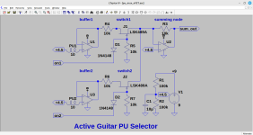
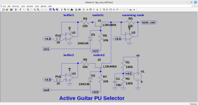
Next I will append a circuit proposal that might point into the direction.
It is evident that you cannot combine active p.u.s.
But you can switch selected buffer outputs to a summing node.
You will learn that doing this analogue stuff is a long road full of tricky details
ending in more or less complex circuitry.
That is why I would prefer to minimize the analogue front end.
Next I will append a circuit proposal that might point into the direction.
Attachments
Ah, I see... The whole idea of these serial/paraller/etc connections is to get that unique sound two or more coils produce in different wirings. When we go into the active low-impedance world, that becomes unnecessary, as what we can only do is to summ the signal of two pickups, like literally "put them next to each other" and balance it. I've red, that there're some kind of modelling circuits, which could be use to "emulate" a series or parallel connection of passive pickups using active pickups, but then we are in the "emulation" word. Even if it is an analog emulation, it's no longer a true circuit.
Thanks for the circuit example, it makes sense to me.
I really wonder, what did they do in the Music Man Game Changer?
When I removed the back cover of my Game Changer Bass, I did few photos. Not great ones, as I wasn't sure what I am for, but still. Maybe it will give us some hints.
That's the whole cavity

So, we have a Pickup connection zone (1). Then, I would guess, since I am not sure: (2) - is the hear of all the switching, probably and (3) is the microprocessor? Or maybe vice-versa. The rest is easy, I guess: active EQ, and 5-way switch
Let's have a close look.
(1):

The bass has 2 humbucker type pickups, which are split in 4 coils. Here we see each of the coils being connected separately as PU1, PU2, PU3, PU4. Why 3 wires? Is it a baseplate ground? So, we have 1 hot and 2 ground signals? Closer look:

Does this wiring ring a bell? There's a transistor, which connects A and B via its legs if I see the track correctly, quite strange to me to connect Hot and Ground, but I may be wrong. What do you see here, guys?
Next, a photo of the (2)

Closer:

You can see, that it is all covered with some layer of "paint", strangely enough not till its very end. And it is not possible to see any marking on the radio elements.
And then from behind:

So, 4 big chips, I first thought those are matrices, but now I think this is the brain of this chain (uProcessor and etc).
Any ideas here?
And the last one (3):

What are these HC 132A PHUY and HC 14A PXTU?
And from behind:
 Are these inductors filtering something?
What do you think?
Thanks for the circuit example, it makes sense to me.
I really wonder, what did they do in the Music Man Game Changer?
When I removed the back cover of my Game Changer Bass, I did few photos. Not great ones, as I wasn't sure what I am for, but still. Maybe it will give us some hints.
That's the whole cavity
So, we have a Pickup connection zone (1). Then, I would guess, since I am not sure: (2) - is the hear of all the switching, probably and (3) is the microprocessor? Or maybe vice-versa. The rest is easy, I guess: active EQ, and 5-way switch
Let's have a close look.
(1):
The bass has 2 humbucker type pickups, which are split in 4 coils. Here we see each of the coils being connected separately as PU1, PU2, PU3, PU4. Why 3 wires? Is it a baseplate ground? So, we have 1 hot and 2 ground signals? Closer look:
Does this wiring ring a bell? There's a transistor, which connects A and B via its legs if I see the track correctly, quite strange to me to connect Hot and Ground, but I may be wrong. What do you see here, guys?
Next, a photo of the (2)
Closer:
You can see, that it is all covered with some layer of "paint", strangely enough not till its very end. And it is not possible to see any marking on the radio elements.
And then from behind:
So, 4 big chips, I first thought those are matrices, but now I think this is the brain of this chain (uProcessor and etc).
Any ideas here?
And the last one (3):
What are these HC 132A PHUY and HC 14A PXTU?
And from behind:
What do you think?
This was a circuit example for 2 p.u. that can be expanded to more...what we can only do is to summ the signal of two pickups, l
Sorry for the confusion. What I meant with this is different: with active electronics or buffered passive pickups, we can't do much of what was the original intention, namely, put coils into the different configurations and exploit the physics of actually COILs being connected in number of ways. What we have with buffered pickups is just a sum of their outputs, which is not the same as the tandem of coils providing high impedance output.This was a circuit example for 2 p.u. that can be expanded to more...
That is true, Keep in mind that the classical wirings were a result of limited technique available at that time.we can't do much of what was the original intention,
Tubes were expensive so p.u.s needed thousands of windings to deliver a maximum voltage -
with the downside of high impedance.
As a consequence cable capacitance of guitar cables alter the sound depending on cable capacitance and coil inductance.
This explains why series wiring of coils yield more voltage, but a darker sound with less treble.
Knowing this many people have experimented with parallelling caps to the coils, usually in the range of100pF~several nF.
This will shift the resonant peak and is indeed an easily audible effect.
I am starting to believe, that the Music Man Gamechanger circuit is emulating all of these "classical" wirings. Not digitally, of course, but I less and less believe, that the physics in the coils making a deal there, but rather a combination of op-amp tricks, analog filters, etc., which makes some wirings to sound like parallel and series. It sounds good, though, and maybe that's the way to go as well.This explains why series wiring of coils yield more voltage, but a darker sound with less treble.
I am curious on whether anyone who looks into those photos above will be able to guess at least approximately, what trick they did there and what technology used.
- Home
- Live Sound
- Instruments and Amps
- Guitar Pickup switching system (using microcontroller)