Is it a good idea to run this driver down into the 20’s? It’s only rated to 50W. I guess that would be OK for my Mom.
Maybe a double woofer system with one crossed over before the little impedance bump? Cover the baffle step and lower bass distortion?
Maybe a double woofer system with one crossed over before the little impedance bump? Cover the baffle step and lower bass distortion?
Just run 2 woofers and a mid-tweet MTM style if you really want to melt the wallpaper. 🙂
jeff
jeff

Certainly a successful strategy with the paper A12PWs & A7sJust run 2 woofers and a mid-tweet MTM style if you really want to melt the wallpaper. 🙂
jeff
I've been curious why I haven't seen seen a dual same driver, with a cap for the high frequency driver and a coil for the low frequency driver.....
Assuming a flat impedance curve also................
I understand that bigger drivers for bass and smaller drivers for better dispersion.
And even smaller drivers "breaking up better" at high frequencies.....
I just see it as a very simple 2-way with more advantages than a 1-way, but at double the cost and slightly trickier driver box mounting......
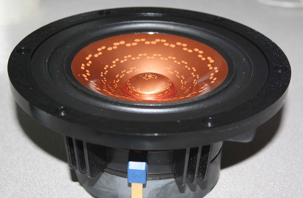
Unless painting with polka dots 😉Superb speaker but don't touch at the cone ! 😱
T
I touched the cone, Ray.Superb speaker but don't touch at the cone ! 😱
T
I touched the cone, Ray.
By my experience, if it is the same material as the Alpair 10.3M, it is very fragile and marks very easily :
This is why I am somewhat reluctant to go for that nonetheless excellent MA-200-8 wide band speaker... 😕
T
Still down with summer 'flu, but a few general thoughts re some of the above. In no particular order:
Bad humour aside -might need more than just a cap & coil depending on the enclosure design & diffraction etc. but not necessarily much.
Well, looking at practical power handling, a basic maximally flat mathematical alignment (which I don't recommend using in practice but good for comparisons) has the driver reaching its 9mm 1-way Xmax at 11w signal input. The large vented standmount I did for it, which is done with a non-exclusive eye to higher output impedance amplifiers, will hit 1-way Xmax at approximately 7w input. So you're never going to get near the thermal coil rating with most vented loads, as you'll run out of mechanical excursion well before that. For comparison, pulling another unit one at random from the virtual shelf, for a max-flat alignment, the Scan 22w/8534G00 reaches Xmax with approximately 2w signal input. It gets a few Hz lower & requires a larger box for that alignment than MA200, which is why I mentioned the large, lower tuned vented standmount I did for the latter so the two cancel out somewhat. The Scan, lest anybody thinks I'm taking a pop at them, is one of my favourite affordable 'soft[ish] cone' 8in midbass drivers. Its coil has a 70w nominal rating & a long-term 120w which are roughly 20w higher than the alloy cone MA, but like the latter, you're unlikely to get near them, even with a Pi-align. Short version: assuming you don't have the mechanical sympathy of Captain Caveman, in most vented alignments, these units are likely to be mechanically rather than electrically limited.Is it a good idea to run this driver down into the 20’s? It’s only rated to 50W.
You know your mum's hi-fi requirements better than any of us of course. 😉 Mine's still a rocker at heart (worships Patti Smith, Rory Gallagher, Robert Plant / Led Zeppelin, Free, King Crimson etc.).I guess that would be OK for my Mom.
Be nice to have -and 'we're' actually hoping to provide separate 'advanced' data sheets in the future for most drive units, as time allows (MA is a small company with few full-time employees, and if they're doing that, they can't be doing something else that's frankly more important, e.g. building drive units that have been ordered). That will include either a polar map and / or directivity index chart, along with additional parameters etc. In fairness to them though -I can't think of many companies who do provide separate directivity plots. Some, yes, but they're thin on the ground, & usually either bigger, or with a smaller model range & selling to a different market / audience.Where is the directivity graphs?
I've got 'flu, man -that's in the pipeline, as I've done with some other units in the past, but give me a bit of a break. 😉I've been curious why I haven't seen seen a dual same driver, with a cap for the high frequency driver and a coil for the low frequency driver.....
Assuming a flat impedance curve also................
Bad humour aside -might need more than just a cap & coil depending on the enclosure design & diffraction etc. but not necessarily much.
Right; MA tend to design some of their larger metal units to start TL operation as low as possible.Transition from pistonic to chaotic radiation in would be my guess. At least thaty is what Mark told me when we were chatting about a similar impedance bump in the EL70.
Last edited:
Scott, there aren't any to/horn enclosures on the page. Is that because they're less priority, or is the driver less suitable? Of course I'm thinking BIB and I can roll my own. But it just caught my eye.
It would be good to have some off-axis info, even if it's limited. Many driver manufacturers provide a couple of off-axis curves on their datasheets - 30 and 60 degrees, often. For a company like Markaudio making full-range drivers, it feels like a big omission not to provide that much. On the subject of limited info, I'd also quite like to know whether the xmax figure that MA supply is intended as a linear or 'before damage' figure (and I appreciate there are several ways of calculating/estimating the former).Be nice to have -and 'we're' actually hoping to provide separate 'advanced' data sheets in the future for most drive units, as time allows (MA is a small company with few full-time employees, and if they're doing that, they can't be doing something else that's frankly more important, e.g. building drive units that have been ordered). That will include either a polar map and / or directivity index chart, along with additional parameters etc. In fairness to them though -I can't think of many companies who do provide separate directivity plots. Some, yes, but they're thin on the ground, & usually either bigger, or with a smaller model range & selling to a different market / audience.
Right; MA tend to design some of their larger metal units to start TL operation as low as possible.
My apologies for not keeping up with your shorthand - by TL do you mean transmission line? (But not to refer to any enclosure, rather to to indicate the propagation of waves across the cone?)
Isn't 450 Hz surprsingly low for a metal cone of this size (about 150mm) to be moving out of pistonic behaviour?
Last edited:
I can't say my inner voice is screaming "shut up and take my money" yet, but I can hear it doing vocal warm up...
Partly because I've got 'flu, partly because I don't provide more advanced enclosures for the MA site, since one such design as far as my time / costs go would cost as much or more than my monthly consultancy retainer.Scott, there aren't any to/horn enclosures on the page. Is that because they're less priority, or is the driver less suitable? Of course I'm thinking BIB and I can roll my own. But it just caught my eye.
As as aside -I've never been fond of using the MA drivers in a BIB type pipe-horn; long-throw, low-mass units with alloy cones are potentially easy to over-drive in that specific type of enclosure. Fine if you go easy of course, and you know what you're doing, so you'd be fine, but when I create designs for the MA site, I generally have to be careful to ensure they're relatively easy to build, and also relatively forgiving / lower risk as most builders won't necessarily be able to ask advice or even realise they may benefit from it. This actually ties into:
Agreed. And it's something MA used to do, which I've regularly requested gets reinstated. I've carried the point (to a, er, 'point') & as noted it will go into the separate data sheets when they're able to create them.It would be good to have some off-axis info, even if it's limited. Many driver manufacturers provide a couple of off-axis curves on their datasheets - 30 and 60 degrees, often.
Sure. MA basically use Gander's Xmax derivation as a rough guide to linear travel, but account for the yoke / washer / plate thickness in that (which isn't always included).On the subject of limited info, I'd also quite like to know whether the xmax figure that MA supply is intended as a linear or 'before damage' figure (and I appreciate there are several ways of calculating/estimating the former).
Right.My apologies for not keeping up with your shorthand - by TL do you mean transmission line? (But not to refer to any enclosure, rather to to indicate the propagation of waves across the cone?)
Depends what you call surprising; thing is -while that's the usual, nobody ever said you 'have' to do that. MA drivers are designed more with an eye to their operating as resonant structures over almost all their BW than most MC drive units; in that they're closer to something like a Manger, BMR etc. Not a perfect analogy, obviously -they do still operate under oscillatory conditions in the LF of course, but the transitional region is broader & to a point fuzzier than is often the case.Isn't 450 Hz surprsingly low for a metal cone of this size (about 150mm) to be moving out of pistonic behaviour?
Last edited:
Is that each or per pair? Who is selling these? Thanks!299 Australian dollar. About ~180 euro.
marks very easily
The metal cone sare very fragilke and easily dented. But a careful touch will not harm them.
I have spent a lot of time “touching” those metal cones.
dave
It would be good to have some off-axis info, even if it's limited
The last (and maybe the only) published info.
dave
The German diy audio magazines do lots of driver tests, also Markaudio. Klang&Ton, HobbyHifi, the online Hifi-Selbstbau. A lot of those back issues and individual tests are available online (paid and legit/legal free). There are excellent off-axis frequency response measurements in those tests. To be honest, even when manufacturers publish frequency response curves, I will always also look at the magazine tests. They may not be better, but at least they are standardized for the publication and so offer the best material for comparison.
So in my personal view, providing off-axis frequency response into is not of the greatest priority.
So in my personal view, providing off-axis frequency response into is not of the greatest priority.
Some of the lowest Mms for a given size class is found in the fullrangers, generally with some lower power handling or xmax than woofers.I bought a pair of 15" Fane full range for cad$178 each several years ago. Vintage balanced system with Klark Teknik parametric and a Bryston 2B amplifier. Dynamic and holographic with life sized, real sounding instruments. Big fan of larger full rangers while accepting the compromises.
Recently I picked up the very inexpensive Sica 10d1cs because of having highest Sd to Mms ratio of nearly any driver I've seen.
The motor is weak, so very undamped bass, not exactly a hifi driver but what stands out is the benign/euphonic nature of its distortion, it is fairly pleasant to listen to.
You know your mum's hi-fi requirements better than any of us of course. 😉 Mine's still a rocker at heart (worships Patti Smith, Rory Gallagher, Robert Plant / Led Zeppelin, Free, King Crimson etc.).
My Mom listening to King Crimson! 🤣🤣🤣🤣🤣 I can party with your Mum though!
- Home
- Loudspeakers
- Full Range
- New Markaudio MA200 8" Driver