https://assets.wolfspeed.com/uploads/2023/11/Wolfspeed_C3D02060F_data_sheet.pdf
I have a lot of these SIC diodes, rated 600V. I would like to use them in a diode bridge instead of the 1200V SIC diodes I usually use for a 350V B+ supply.
So I need equalising resistors. What value and wattage should these be?
Do I need caps as well? If so what type and value?


I have a lot of these SIC diodes, rated 600V. I would like to use them in a diode bridge instead of the 1200V SIC diodes I usually use for a 350V B+ supply.
So I need equalising resistors. What value and wattage should these be?
Do I need caps as well? If so what type and value?

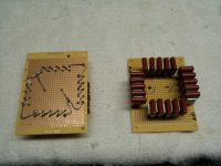
Pics aren't díode bridge.
I never seen resistors paralleled to bridge diodes, caps are usually 0,1uF but believe me with Sic aren't needed.
I never seen resistors paralleled to bridge diodes, caps are usually 0,1uF but believe me with Sic aren't needed.
Pics show diodes in series with equalising resistors. Obviously there are 4 of these in a bridge.
The diode bridge should output around 350V B+ at around 150mA.
I thought equalising resistors were required to equalise the diodes? I don't want the bridge to blow up!
I thought equalising resistors were required to equalise the diodes? I don't want the bridge to blow up!
https://www.nutsvolts.com/questions-and-answers/diodes-in-series
Seems to be explained here. This example is pretty close and uses 10M equalising resistors.
Seems to be explained here. This example is pretty close and uses 10M equalising resistors.
I run 5 1200V SiC diodes on each leg of my Amp rectifier bridge putting out 2.3kV at the tube anode, much higher voltage peaks at the rectifier. No EQ resistors, just 1250V 10nF caps across each diode. Haven't had an issue in 10 years.
PS: I removed the copper pads between the connections and coated the back in corona dope after that picture was taken, so no issues with HV jumping between pads.
PS: I removed the copper pads between the connections and coated the back in corona dope after that picture was taken, so no issues with HV jumping between pads.
Attachments
They are quite high capacitance, so some resistors might be helpful, But the Rs must withstand 600V - so end up being a hassle too.
BTW, At 350V 150mA DC and below, the SiC diodes are not worth the trouble. They may have zero reverse recovery time, but the capacitance (around crossover) is rated >150pF. This is unhelpful when the leakage inductance of the PT is getting twanged all the time.
Meanwhile, UF4007 diodes are fully insulated, rated 1000V, small & flexibly mounted, low enough recovery charge; -14dB lower capacitance - (30pF) at crossover - and ... 40dB cheaper.
Buy a bag of these when you are out shopping.
It would be easier to build without the resistors. I built a bridge with the 600V SIC devices in series and that seemed to work OK.
I do have some UF4007. Haven't compared them to the SIC diodes to see if I can hear any difference.
I do have some UF4007. Haven't compared them to the SIC diodes to see if I can hear any difference.
andyjevans was right to be concerned . . .
A few simple calculations:
A capacitor input filter that has 350VDC B+ . . .
The secondary winding has to supply 350V Peak to the rectifier.
Even for a bridge, one diode at a time will see . . .
+ 350VDC in series with the secondary that is now at -350V = 700V Peak Inverse voltage across the diode.
A diode rated at 600V Peak Inverse Voltage . . . can survive 700V Peak Inverse Voltage, But Only if you go to church every Sunday, and pray real hard.
Just my $0.02
I need to purchase some more of those expensive HEXFRED diodes. They always worked, when lesser diodes blew up.
8A3sUMMER - thanks! That's exactly what I thought - you need 2x diodes at 600V in series.
The question is whether you need equalising diodes, and if so what value and wattage.
I have a lot of these SIC diodes, so I need a safe solution!
The question is whether you need equalising diodes, and if so what value and wattage.
I have a lot of these SIC diodes, so I need a safe solution!
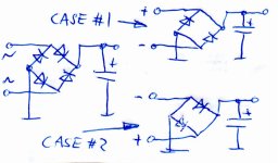
That is certainly true for the 2 diode CT FW rectifier, but not for a bridge,Even for a bridge, one diode at a time will see . . .
+ 350VDC in series with the secondary that is now at -350V = 700V Peak Inverse voltage across the diode.
where the two forward biased diodes always connect the two reverse biased diodes with the cap.
So the secondary is never in series with the cap.
That doesn't mean that you cannot play it safe and use 2 diodes per leg.
I have never seen balancing resistors in a commercial product, and I wonder what they are supposed to balance ... ?
Attachments
The resistors are used to swamp out reverse leakage currents of the diodes so that the reverse voltage divides equally across the two diodes. If the leakage currents were unequal, then the reverse voltage would not divide equally across the to diodes, cause failure of the less leaky diode first, followed by the leakier one. Caps are not needed with SIC diodes due to their near-zero reverse recovery time.https://assets.wolfspeed.com/uploads/2023/11/Wolfspeed_C3D02060F_data_sheet.pdf
I have a lot of these SIC diodes, rated 600V. I would like to use them in a diode bridge instead of the 1200V SIC diodes I usually use for a 350V B+ supply.
So I need equalising resistors. What value and wattage should these be?
Do I need caps as well? If so what type and value?
View attachment 1345444View attachment 1345445
The capacitors are there to swamp diode to diode capacitance variation, which affects the voltage sharing when switching, nothing to do with reverse recovery. I would really want to avoid this circuit as reverse leakage can get high enough to require rather low value resistors. Definitely not 10M.
When the diodes are reverse biased, different leakage currents will cause uneven reverse voltage sharing, leading to possible failure. Capacitance variation between the same type diodes has not been a problem. They (R's) are simply not needed when the diodes start forward conduction.
I recall just this thing in the early 1970s. A high school amateur radio friend was building a high-voltage power supply (for a tube-based transmitter, no doubt) using many series diodes (not sure, but I presume 1N4004, 200V PIV, at the time I didn't know if higher voltage rectifiers were non-existent, or just really expensive). Each diode had a .01uF cap and a 470k resistor across it. For 600V parts I'd probably use two resistors in series, maybe adding to 1 meg or so, and of course 600V+ rated caps. No doubt there's a schematic of this in a 60's or 70's ARRL Amateur Radio Handbook.
Some posters imply this is unnecessary, but I'd consider it cheap insurance.
Some posters imply this is unnecessary, but I'd consider it cheap insurance.
I remember Semikron recommended to use resistors as well a RC snubbers in paralell to theyr high power silicon rectifiers when voltages dictated to use serial connection. The resistors where needed to assure equal voltage sharing. Also, because of the often quite large leakagecurrent spread, and to keep the losses in those resistors down, the voltage had to be derated quite a bit.
I migth still have the formulas provided by Semikron somewhere, but I never used shunt resistors, nor snubbers, just plain 0.1uF caps across each diode and heavy voltage derating (3 phase bridge, 12kV 20A rf-heater load, 96 1.2kV 70A diodes and caps in total). Despite the overrrating, sometimes some diodes failed, mostly do to the vibrations transmitted through the floor from the press to the caps (legs broke off). When that happ3nd, the diode dyed, and it happend more than once that some of the factories electricians changed the cap or/and the dead diode into a different one. Regarding equal voltage distribution this was was not always the best idea. A lower voltage, or capacity cap is offcourse ligther and withstand vibration better, but the 1kV/0.1uF was allready about the smallest usable size , and when only parts of the chain where exchanged into unequal ones the whole chain was in danger to brake down. And that happend quite a few times over the decades.
All of that changed after replacing the rectifier diodes with ones that have controlled avalanche breakdown no diode shunt components are needed.
Last edited:
- Home
- Amplifiers
- Tubes / Valves
- High voltage SIC diodes in series + equalising resistors