
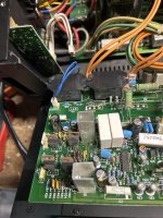
Yes, and the large cubic white ones, for example the couple beside one of small the silver heatsinks. Possibly also all the small yellow ones.I will check the relay DC offset once I get home. As for the white film caps, are you referring to these? I count two of them on the board.
View attachment 1344197
Are you sure? Pin 4 is the speaker output after the relais, so if the relais does not engage, how can be a voltage there... pin 5 is amp output.I checked DC offset going into both relays.
I am getting 30V into the coils 1 and 2
Pin 4 I am seeing -21V. Same result for both relays.
I image that is what is causing the relay to not engage.
I would first measure DC offset to ground on one of those green 0,22 ohm resistors. --> 21V ?
Then, the mV across one of those resistors to see if there is an idle current. Compare to the working channel. Both heatsinks getting warm ?
Next: Input stage rails and +/- 15V supply of the AD711 are ok ?
Those film caps are everywhere, they could short one of the opamp rails or short the bias voltage of the output stage.
If all rails and film caps are good, look at the input fets, the IRFs, opamps, power resistors...
You could either first encircle the problem by measuring all crucial voltages in live circuit, if you feel comfortable with the 90V rails..., or just check each and every part, one group after another. Caps, Transistors, resistors, ICs.
Examples of shorted film caps: B+ for the opamp shorted to ground, input stage cascode voltage shorted to ground.

There are only 4 Pins on this relay. I wonder if the schematic has the numbers mixed. I checked the lay-out of the relay and it is definitely Pin #4 giving me -21V. Unless I missed a small tab that is still soldered to the board that would be pin #5. I will check this again.Are you sure? Pin 4 is the speaker output after the relais, so if the relais does not engage, how can be a voltage there... pin 5 is amp output.
I would first measure DC offset to ground on one of those green 0,22 ohm resistors. --> 21V ?
Then, the mV across one of those resistors to see if there is an idle current. Compare to the working channel. Both heatsinks getting warm ?
Next: Input stage rails and +/- 15V supply of the AD711 are ok ?
Those film caps are everywhere, they could short one of the opamp rails or short the bias voltage of the output stage.
If all rails and film caps are good, look at the input fets, the IRFs, opamps, power resistors...
You could either first encircle the problem by measuring all crucial voltages in live circuit, if you feel comfortable with the 90V rails..., or just check each and every part, one group after another. Caps, Transistors, resistors, ICs.
- I checked all the .22 ohm Green resistors and all of them showed 21V. I also checked the rails for each mosfet and they all showed 90V.
- I confirmed the heatsinks were getting warm on the bad channel.
One big discrepancy I saw while I was taking measurements last night was on Q5 and Q6 (IRF610). I powered on the working channel and compared the voltage on the heatsinks that are attached to the drain. I was getting about 2Volts on the working channel Drain to ground and 18V on the bad channel.
Here is what I will check tonight:
- Input stage rails and +/- 15V supply of the AD711 are ok
- Check all the 33V Zeners
- Check all the film caps for failures (the white ones should be easy by just de-soldering one leg and checking continuity)
- I am trying to understand your graphic on post #25 and how you would recommend I measure for faults here.
So if the good and bad channels have a similar temperature after 30 minutes, I would cautiously assume that the bias generator / output stage part of the schematic starting with C18 is ok.I confirmed the heatsinks were getting warm on the bad channel.
You could measure the millivolts across one 0.22ohms on each channel to 100% confirm that.
There is + rail --> R92 --> 15V zener --> ground.I am trying to understand your graphic on post #25 and how you would recommend I measure for faults here.
So, on the junction of two parts is 15V, filtered by a lytic and two film caps.
If a film cap is shorted, the zener is bypassed and the 15V collapses, so the + rail for the AD711 missing.
Same with the cascode voltage...
Encircled in red are the film caps, blue is the resulting "short" DC path to ground
No need to desolder. The continuity check with beep of any DVM will quickly charge a possibly parallel connected lytic cap, so you may get a short beep with corresponding low ohm reading that you can ignore. Permanent beep is a failed cap. Scratch a bit back and forth with the tips to make sure it has contact.Check all the film caps for failures (the white ones should be easy by just de-soldering one leg and checking continuity)
Last edited:
Best measure the voltages on all 3 pins of that IRF610 on both channels.
Also voltages across R31 and R33 should be 0.15V as per schematic the current is 15mA.
Input stage rails 99V ?
Also voltages across R31 and R33 should be 0.15V as per schematic the current is 15mA.
Input stage rails 99V ?
Here are some more readings I took. I hooked the amp back up after it being in a cool environment and noticed the working channel DOES get warmer while the damaged channel, not so much. It was just warm from being in my garage when I felt it last night. So I don't think the bias stage is working correctly.
Across the 0.22 resistors I got 4mv on the working channel and 1mv on the problem channel
Across resistors R31 and R33 I got 73mv (not 0.15V)
I checked the Positive input on the AD711 (pin#7) and got 15.68V (so that is correct)
I checked all three pins on Q5 and Q6
Across the 0.22 resistors I got 4mv on the working channel and 1mv on the problem channel
Across resistors R31 and R33 I got 73mv (not 0.15V)
I checked the Positive input on the AD711 (pin#7) and got 15.68V (so that is correct)
I checked all three pins on Q5 and Q6
- Q5 is GDS - 89V, -18V, 95V (Pin D on the working channel is +2V)
- Q6 is GDS - -94V, -23V, -96V (Pin D on the working channel is -2V)
-89 is a typo ? 89 is right ?Q5 is GDS - 89V, -18V, 95V (Pin D on the working channel is +2V)
and the negative rail ? Pin#4 = -15V ok ?I checked the Positive input on the AD711 (pin#7) and got 15.68V (so that is correct)
Pin#6 around -12V ?
How about the film caps ?
Last edited:
What is printed on yellow R46 ?
Is the input switch set to chinch ?
I would check voltages on the red dots.

Is the input switch set to chinch ?
I would check voltages on the red dots.
Yes. Typo, it was +89-89 is a typo ? 89 is right ?
and the negative rail ? Pin#4 = -15V ok ?
Pin#6 around -12V ?
How about the film caps ?
Negative pin 4 on the opamp looks wrong. Shows -0.775V
I checked all I could see on film caps and non were shorted.
So please check again voltage on pin 4 of AD711 and on D6 which powers the V- of the AD711.
If it is really -0.775V, then either the 15V zener or one of the three caps or the AD711 or the NJM074 has a short. Or R93 is open --> check.
If it is really -0.775V, then either the 15V zener or one of the three caps or the AD711 or the NJM074 has a short. Or R93 is open --> check.
Looks like somebody was in there before and C7 is missing. The 100µF / 25V Black Gate was suspected to have a short, which was not true.
So check those other parts.

So check those other parts.
Sorry. I was the one that removed that capacitor (C7) to test it. I mentioned that in the post with the image. It has been back in there for all my readings.
Pin 4 is definitely +0.775V.
The diode D6 is also showing the same thing at the Anode.
Just pulled R93 and it is open!
Pin 4 is definitely +0.775V.
The diode D6 is also showing the same thing at the Anode.
Just pulled R93 and it is open!
- Home
- Amplifiers
- Solid State
- Parasound HCA 3500 -- Part it out or Get it fixed?