I always wondered why tube audio amps do not use plate parasitic suppressors. It would be about 20 turns of 1/2" wire. Likely start suppressing at 100kHz (guess)
For most tubes/circuits, the use of a grid stopper and screen stopper alleviates any local feedback for uncontrolled oscillation. When I use 807's I also typically add a plate stopper, and have even used slip-on emi ferrite beads to add resistance beyond 1Mhz. The ferrite material for beads needs to be known to confirm when they start to become significantly resistive, and a good choice is for beads/tubes designed for emi suppression.
I think you mean 1/2" diameter turns, not 1/2" diameter wire!!!It would be about 20 turns of 1/2" wire.
I included these plate suppressors as the default with finals that have plate top caps since this leads to longer runs between the plate caps and the primary of the OPT. This was with the 807 and the 6BQ6. The STC 807 Report does recommend plate suppression for audio applications. As for whether or not the 6BQ6 needs them, who knows? The spec sheet makes no mention of using the type as an audio final. You probably won't need them when using types that bring out the plate connection under the chassis as you can keep the leads to the OPT shorter.I always wondered why tube audio amps do not use plate parasitic suppressors. It would be about 20 turns of 1/2" wire. Likely start suppressing at 100kHz (guess)
The plate suppressors I used are specced: N= 10; #18AWG; ID= 7/16 inch. Include 100R/2W C-comp resistors in parallel with the coil, and mounted inside the coil. If 100R/2W resistors aren't available, then four 470R/0.5W C-comps are used instead.
807s definitely need screen suppressors: 1.0K, C-Comp since the 807 likes to make snivets at plate current cutoff. Without the screen suppressors, I got ringing at ~60KHz at the zero crossings. The 1.0K screen stoppers fixed that.When I use 807's I also typically add a plate stopper, and have even used slip-on emi ferrite beads to add resistance beyond 1Mhz.
Alot depends on layout, although using the surplus PL tube series, I often got snivet interference; and on one amp I built, the issue was quite pernicious. Tinkering with the o/p stage from tetrode to UL operation using every stopper in sight was no solution, the snivets varied fom 60Khz to 3MHz; invariably with long anode leads and other tube interactions doesn´t help. When the power got going, the interference symptoms shifted upward in frequency, very similiar to some nasty class B op amps exhibit i.e LM380.I always wondered why tube audio amps do not use plate parasitic suppressors. It would be about 20 turns of 1/2" wire. Likely start suppressing at 100kHz (guess)
By chance, I had some largish medium permeability 3S1 ferrite toroids (Philips) which managed to fit inside the ceramic top caps (or if a little protruding) secured with high temp oven adhesive. This solved the snivet issue, but I cannot say this is the solution for other designs. Touch and go it is, perhaps an already `close" design. Maybe a lower permeability ferrite material would be more suitable but all open to experimentation. Barkhausen effect;.
We have the output transformer choke or inductance with an inherent self resonance frequency is ready to go, so as I see it the high frequency snivet problem is more of circuit radiation or the circuit boundary parameters exciting the equivalence of Barkhausen within the tube. The Radiotron Hd bk 4th ed, p.547 is a taster, (not a solution) but also reading the operative remarks on the PL519 spec sheet worth a peep.
Ironically, burning much midnight oil doing much circuit surgury, swapping the PL519 for a KT90, the snivet problem vanished. It is already known that the KT90 is a re-engineered, upped´ PL519, with electrode parameters more suited for audio circuitry, so that solved it. The snivet problem can be a tough nut to crack with sweep tubes. In some cases with bench work, beware that the slight capacitive loading of some X10/x!00 scope probes may stop circuit oscillation, creating even more mystery looking for an unknown. The solution here is to use a sniffler coil close to the tube. If the circuit radiates, it will pick the RF up.
Bench Baron

One reason that Hi Fi Audio Amplifiers with 807 Output Tubes do Not use those coil-on-resistor Plate parasitic suppressors . . .
In Hi Fi, the [assumed] expectation is that the volume control is adjusted to keep the amplifier from going into Hard Clipping.
Hard Clipping causes the 807s to go Into Cutoff, and Beyond Cutoff.
Cutoff for an 807 is just fine, as long as it is used in a Class C RF amplifier. It is designed to do that.
And, in that case, the use of a parasitic suppressor is paramount.
If all Electric Guitar amplifiers used 807 output tubes, then . . .
If the amplifier was played by Dan Balmer, it does Not need a parasitic suppressor.
But if the guitar amplifier was played by Jimmy Hendrix, it Does Need a parasitic suppressor.
Can you see the difference?
All the above is just my opinions and experience.
Yes, I have been exposed to high level RF, that did mix up my brain a little bit.
I worked in RF gear and antennas all the way from 150kHz to 500GHz (Yes, 1/2 a TerraHz).
Hint:
When one tube of a push pull output stage goes into cutoff, the associated 1/2 of the primary winding is "flapping in the breeze". . .
The reactances of the Distributed Capacitance and the Leakage Inductance of that 1/2 of the primary are free to do whatever they want . . .
Resonate, and generate extra high voltage oscillations.
I suspect that this high voltage oscillation at the cutoff plate, may be partially responsible for the screen oscillations.
Sometimes the high voltage goes high enough to temporarily go back out of cutoff, and then back into cutoff.
Be sure to consider the Leakage Inductance from one 1/2 primary to the other 1/2 primary,
(Not Just the more commonly considered Leakage Inductance from the primary to the secondary).
Also consider the capacitance of the 1/2 primary to the secondary, and to the laminations.
Not all is as simple as it first seems.
Last edited:
In order to get RF oscillations for one just needs a poorly damped resonance and a source of energy. Anything the universe can do to dump energy in some place other than where it is desired - it is going to do it. If the load impedance goes high enough and driven into hard saturation (which is good for RF efficiency and also what happens with Jimi Hendrix’s guitar Playing) you simply put the screen into its region of negative resistance.
Its not the “cut off” tube that does it - it’s the other side actually, where it’s driven below the knee.
This isn’t the 807 specifically, but all beam power tubes do this. To various extents. With “audio” tubes the plate characteristic has a kink there and the screen doesnt (or has very little). With sweep tubes or RF amps it’s the screen that has the kink and the plate is clean.
With solid state the mechanism is different but results are similar. And sometimes VERY hard to get rid of it.
Attachments
wg_ski,
Interesting.
Thanks!
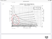
I have noticed that some Kinkless Tetrodes (KT tubes) have negative resistance in their curves.
So much for 'Kinkless' (perhaps Less Kinky?).
The Kinkless Tetrodes employ Beam Formers (KT66, 77, and 88). Including the filament/cathode structure there are 5 tube elements.
Sometimes it is the Screen curves that are Kinky; and sometimes it is the Plate curves that are Kinky too.
Check out the plate kinks in some the graphs of the KT88. Link:
KT88.pdf
On the other hand, True Tetrodes (more often RF than not RF), including the filament/cathode structure, there are 4 tube elements (thus the name Tetrode).
I designed and built a 4-65A Tetrode amplifier; but I used it a an unusual way so that it would act as a true triode..
I grounded the plate. Then I used the 10 Watt dissipation screen as if it was the plate of a triode.
Triode like plate curves, but Not the usual 'Triode Wired' connection from the screen to the plate.
As to windings "ringing" but not the tube oscillating, I suspect there is ringing.
When a 1/2 secondary is flapping in the breeze (from the cut off tube), it is going to resonate according to the Leakage Inductances and various capacitances.
I first worked on circuits that had solid state negative resistances in 1968 . . . the Tunnel Diode. Tektronix used them in their oscilloscope trigger circuits.
In 1985-1887, I worked in engineering on the then un-introduced 2782 spectrum analyzer. The variable resolution filters employed 6 negative resistance amplifiers to drive the 6 crystal filters. That kept the losses down, and reduced the amount of noise figure degradation.
I was in marketing in 1989 when Tektronix introduced the 2782.
Finally! Tektronix had something that could not only meet, but could beat the HP flagship
(the unquestioned leader of the time), HP's 8566B spectrum analyzer.
Interesting.
Thanks!
I have noticed that some Kinkless Tetrodes (KT tubes) have negative resistance in their curves.
So much for 'Kinkless' (perhaps Less Kinky?).
The Kinkless Tetrodes employ Beam Formers (KT66, 77, and 88). Including the filament/cathode structure there are 5 tube elements.
Sometimes it is the Screen curves that are Kinky; and sometimes it is the Plate curves that are Kinky too.
Check out the plate kinks in some the graphs of the KT88. Link:
KT88.pdf
On the other hand, True Tetrodes (more often RF than not RF), including the filament/cathode structure, there are 4 tube elements (thus the name Tetrode).
I designed and built a 4-65A Tetrode amplifier; but I used it a an unusual way so that it would act as a true triode..
I grounded the plate. Then I used the 10 Watt dissipation screen as if it was the plate of a triode.
Triode like plate curves, but Not the usual 'Triode Wired' connection from the screen to the plate.
As to windings "ringing" but not the tube oscillating, I suspect there is ringing.
When a 1/2 secondary is flapping in the breeze (from the cut off tube), it is going to resonate according to the Leakage Inductances and various capacitances.
I first worked on circuits that had solid state negative resistances in 1968 . . . the Tunnel Diode. Tektronix used them in their oscilloscope trigger circuits.
In 1985-1887, I worked in engineering on the then un-introduced 2782 spectrum analyzer. The variable resolution filters employed 6 negative resistance amplifiers to drive the 6 crystal filters. That kept the losses down, and reduced the amount of noise figure degradation.
I was in marketing in 1989 when Tektronix introduced the 2782.
Finally! Tektronix had something that could not only meet, but could beat the HP flagship
(the unquestioned leader of the time), HP's 8566B spectrum analyzer.
The two halves of the transformer are coupled, and the active half is supplying energy on each audio cycle to make the inactive half ring. It’s like striking a bell each time you go thru the negative resistance region, making the circuit produce a (poorly damped) ring at its natural resonance each time. On a spectrum analyzer, it shows up as a sustained oscillation. It takes being driven by a large signal to make it happen. Just sitting under bias all is quiet.
Like all transformers, the windings are coupled.
All transformer couplings are equal; some transformer couplings are more equal. With credit to George Orwells "Animal Farm".
I have previously pointed out the imperfect coupling from the Center Tap to the Ultra Linear Tap; Versus the Ultra Linear Tap to the Plate Tap.
This can be measured at high signal frequencies, whenever there is a phase difference between the screen signal phase and plate signal phase.
If I remember my basic electronics theory from when I did some basic electronics courses at my local university here in Darwin NT Australia, there are two basic requirements for an electronic amplifier circuit to oscillate:
1, The gain in the circuit has to be greater than 1.
2, The total phase-shift from the input to the output has to equal 360 degrees.
If those basic requirements are fulfilled at any one frequency, the amplifier will have a tendency to self-oscillate at that frequency,
1, The gain in the circuit has to be greater than 1.
2, The total phase-shift from the input to the output has to equal 360 degrees.
If those basic requirements are fulfilled at any one frequency, the amplifier will have a tendency to self-oscillate at that frequency,
A fire is often generally described as the addition of Fuel, Oxygen, and sufficient Heat.
An oscillator is generally described as Gain and Feedback (feedback of the phase required to create the oscillation).
Take away any and all forms of feedback: intended, and not intended, and you are left with Gain; it's often an amplifier.
Improper wiring dress can provide the feedback to sustain oscillation.
And so can a powerful signal ground loop that impinges on a small signal ground loop. (Input stage ground loop; output stage ground loop)
Murphy' Law:
Design a power amplifier, and get an oscillator.
Design an oscillator, and get an amplifier.
Take an amplifier that is inverting from input to output (180 degrees). Add feedback from output to input, that is phase shifted by 180 degrees.
That is an oscillator.
Take an amplifier that is non-inverting from input to output (0 degrees). Add feedback from output to input that is phase shifted 0 degrees.
That is an oscillator.
Last edited:
If exactly calculating the phase vs frequency of the returned (feedback) signal - including all the unintended paths and coupling mechanisms - were easy, amplifiers wouldn’t oscillate.
Actually, that is not correct. When you say "the gain in the circuit" I assume that you mean the closed loop gain; that is, the overall gain of the amplifier with the feedback loop connected. Almost all amplifiers will have "gain" as you describe it and most will be stable.If I remember my basic electronics theory from when I did some basic electronics courses at my local university here in Darwin NT Australia, there are two basic requirements for an electronic amplifier circuit to oscillate:
1, The gain in the circuit has to be greater than 1.
2, The total phase-shift from the input to the output has to equal 360 degrees.
Trouble arises at a frequency where the "loop gain" is higher than unity and the phase shift around the loop is 180 degrees or greater. It is naturally assumed that you want the feedback to be negative so the nominal phase shift around the loop is 180 degrees, or inverting. An additional 180 degrees of phase shift will make the feedback positive. So loop gain and phase margin are what matter with respect to stability, not closed loop measurements.
Here is a link that explains this in plain language. It also describes how to apply frequency compensation to make a feedback amplifier stable.
Fun With Tubes - Amplifier Compensation
Exactly finding the transformer's phase shift versus frequency . . . that is more accurately done with a Vector Network Analyzer, or similar measurement tool.
Caution:
Measure it with a driving impedance of the tube or tubes that will drive the transformer primary, and then load the 8 Ohm tap with a non-inductive 8 Ohm load resistor.
Get the accurate results. (*)
Then, Measure it again with a driving impedance of the tube or tubes that will drive the transformer primary, and then load the 4 Ohm tap with a 4 Ohm non-inductive load resistor.
Get the accurate results. (**)
If the phase results of the 8 and 4 taps above do not agree, it is quite likely that the Inductive reactance of the primary to secondary is not at the same ratio as the secondary tap impedances (not 8:4 [not 2:1]).
Then, consider that many loudspeakers load the transformer with widely varying degrees of phase, and widely varying degrees of impedance.
That changes the phase at the secondary, which is the signal that is used for global negative feedback.
Hard Work:
Transformers are not always simple.
Compensation of global negative feedback is not always simple.
But the effort to compensate for your speakers and/or many loudspeaker models is rewarding!
Another Signal Path, Forward Facing:
I worry less about those things now, because I gave up Global Negative Feedback years ago.
Oscillators . . . Not from my amplifiers.
Last edited:
Yes, I did mean the closed loop gain, thanks for pointing that out, cheers.Actually, that is not correct. When you say "the gain in the circuit" I assume that you mean the closed loop gain; that is, the overall gain of the amplifier with the feedback loop connected. Almost all amplifiers will have "gain" as you describe it and most will be stable.
Trouble arises at a frequency where the "loop gain" is higher than unity and the phase shift around the loop is 180 degrees or greater. It is naturally assumed that you want the feedback to be negative so the nominal phase shift around the loop is 180 degrees, or inverting. An additional 180 degrees of phase shift will make the feedback positive. So loop gain and phase margin are what matter with respect to stability, not closed loop measurements.
Here is a link that explains this in plain language. It also describes how to apply frequency compensation to make a feedback amplifier stable.
Fun With Tubes - Amplifier Compensation
I'm not a fan of some aspects of the link in post #374. Imho the 'lead compensation' aspect and the interpretation of Fig.8.1 may not be appropriate. Fig. 8.1 indicates a resonance close to but above 100kHz, and likely related to the 200kHz resonance in the gain-phase measurement plot. I'd suggest it would have been better to remove the 6n8 lead cap and start with a base closed loop squarewave test, as that may have shown just a dominant ~200kHz resonance (which would likely be a significant but damped resonance response depending on feedback level, but not outright oscillatory-unstable), which would then suggest the lead comp should have a corner frequency above that resonance such that the phase margin is improved down at 200kHz, but the gain profile change is insignificant at 200kHz.
That then is a good start to checking whether the amp can be made unconditionally stable for no load and capacitor only load, and what level of feedback can be endured.
There may certainly be output transformers that need very heavy lead compensation, but imho they may be better managed with step network lag compensation, and only minor modification using lead compensation.
I didn't mean to suggest that the link was the last word on how to frequency compensate an amplifier. The intent was to point out that it is loop gain, not open loop or closed loop gain, that is relevant in stability analysis. I'll bow out of the conversation now.
Ray Waters, I appreciate that you posted the link - any discussion is good discussion, as the general topic is very broad and no single OPT and circuit topology covers all experiences. Textbook concepts of stability and analysis, and clear examples of amplifier performance with lots of measurement and awareness are few and far between. It's obviously a difficult and often bewildering road for those diyers starting to broach the issue, and the consequences.
Yes, correct- I find bigger the tube output transformer, even good known makes with optimized sectional windings, particulary 100W power upwards, with UL taps, the transformer parasitics 9 out of 10 require lead/lag circuit network between the first and driver stages also a step circuit in the global feedback loop when modest amounts of feedback 20-25dB are used. I can well understand some amp builders keeping things simple as this is no easy issue trying to optimize for varying loads capacitive and inductive, and the situation can get quite tricky.That then is a good start to checking whether the amp can be made unconditionally stable for no load and capacitor only load, and what level of feedback can be endured.
There may certainly be output transformers that need very heavy lead compensation, but imho they may be better managed with step network lag compensation, and only minor modification using lead compensation.
Lab/ Pit wise, it requires careful use of a signal generator sine/square down to 1Hz with much other equipment. A storage or long persistence scope is vital here. As a taster to the issues, I can recommend reading the Williamson amp, issue from the late 1940´s and the circuit was reworked during the 1950´s. The article appeared via Diyforums but cannot locate it.
It may seem an irony, that even though I am a long time curator of parallel push pull, one would think fewer primary turns is beneficial, in terms of increased bandwidth, yes; lower winding resistance etc, and with less parasitics generally, but as the frequency bandwidth goes up, so do the problem issues. As others rightly mentioned, the amp stage layout must be absolutely sequential with the output sections and wiring well away from the inputs. Even that global feedback connection must be shielded raises another problem.. Amplifiers in the higher power class, typically my 50W-200W parallel KT90 P_P switchable from 300V to 600V confuses many stability diagrams, that in reality I settle on my long experience which often uses an anode to anode snubber...(this requires top grade components). One of the reasons I
don´t submit circuit diagrams.
Although the output tranny may have an excellent bandwidth to 70Khz or so, in the real world the sound fidelity is excellent, I often settle and trim for 40khz for peace and quiet.
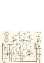
In attachment, an excellent sounding small amp that was on the verge of violating operating conditions I once listened to, was a class A red hot glowing EL84 amp from an unknown record player which used the bass control in the global feedback loop. Plug in a second speaker and it oscillated. constructors be wary of this type of design that enamated around the early 1960´s: Simple, but it can also make one howl of protest !
Bench Baron
Attachments
- Home
- Amplifiers
- Tubes / Valves
- Oscillation in tube amps