I don't understand what "max A" or "coil A" is here.Switch ON: the surge current charge the coil (max A measured to size the coil A, uH sized appropriately to let it charge and discharge in a duty cylce without saturation)
The current in an inductor is the integral of the applied voltage. So with a constant voltage applied, the inductor current will rise linearly.
You can consider the inductor to be a battery as you've drawn the moment the diode begins to conduct. The inductor will then 'see' a voltage of VL = Vin-Vout, and since Vout > Vin this means the current in the inductor will decrease linearly. It also means that the voltage across the inductor will be constant as long as the current flows.
The two different operating modes, constant current mode (CCM) and discontinuous current mode (DCM) refers to the inductor current. In CCM there's always current flowing in the inductor. In DCM the inductor current goes to zero at some point during the switching cycle. At this point neither the MOSFET nor the diode will conduct and the load current is provided entirely by the output capacitor.
As pointed out above you need to run the converter in DCM if you want it to boost 12 V to 400 V, so you need to pick the inductance accordingly.
Also note that the loop gain changes when the converter goes from DCM to CCM so you want to make sure that doesn't happen if you want the control loop to remain stable.
Thanks. I've been into electronics since I was about five years old. That helps... I'm 20 dB older now. 🙂You are a well of knowledge.
Yeah. The 555 was invented shortly after the invention of dirt, but the UC38xx is not much younger. It was originally made by Unitrode. TI acquired Unitrode in 1999. I used the UC38xx at that time.Also, 555 is old, cheap but not so cheaper than UC38xx. I prefere to work with state of art IC if possible.
Basically, yes. The transformer gives you greater flexibility because you can decide on a turns ratio that works for you. That would allow you to run the converter in CCM, which can have some advantages. Like lower output ripple voltage if I recall correctly.[IS THE FLYBACK SCHEMATIC HERE AN ISOLATED VERSION OF MY SMPS SCHEME? AT MY EYES SEEMS SO]
It's not super hard to design a transformer, but getting materials to build them can be a challenge. I suggest you get your feet wet with a non-isolated SMPS first.
Tom
Are you 65? I used to measure age time in years xDThanks. I've been into electronics since I was about five years old. That helps... I'm 20 dB older now. 🙂
Indeed I need to study better RLC circuits and physic behind. Unfortunately in my study path (scientific high school and chemistry bachelor), also physic professor was afraid to introduce L (seems complicated for them too) 🙂
Well, if I scrap parts form old trafos? In my DIY head, modify a transformer seems relatively easy. Make a trafo that has a ratio Power/Dimensions high is the challenge.It's not super hard to design a transformer, but getting materials to build them can be a challenge. I suggest you get your feet wet with a non-isolated SMPS first.
Btw, I would a thing that is small. So I try to improve initial schematic. The safety is achieved by a fast discharge of caps after unplugging of 12V dc (3-5 seconds) and a well isolated case and circuitery.
I mean: based on all parameters (Vin, D, mosfet, etc) the coil will experiment a insurge current, max A(mphere).I don't understand what "max A" or "coil A" is here.
Coil A is the coil amphere rating.
Like 100uH 5A coil, 10uH 3A coil, etc...
Nah... Only 20 dB (10x) more than 5. I'll be 50 in two weeks.
Typically the symbol I is used for current. Or i for small-signal. A current, I, is measured in ampere, A.
I wouldn't focus on RLC circuits. I'd look specifically at the equations for the voltage across an inductor. Then, as done in the article I linked to, approach the SMPS in its two (or three) states: MOSFET on, diode on, neither on (for DCM).
I wouldn't bother with a fast discharge circuit. Just add a high-ohm bleeder on the output. The bleeder and the load will discharge the supply just fine, especially once the switches stop switching. Do be careful with the high voltage, though.
Tom
Correct.At the CONTROL pin of the mosfet switcher I could connect a 555 or a proper IC like UC38xx. That is what you mean, @Bluesystems?
The spice source I show assumes a current controlled switcher IC (like the UC3845) running from 12V is driving the MOSFET gate at the maximum duty cycle of 50% with a switching rate of 100Khz.
My sim just shows the "meat" of the switcher, with suggested capacitor value, inductor value, Mosfet and the diode.
The capacitor would be best as a film part.
Why use a a maximum duty cycle of 50%? This is a very important point for audio applications.
The UC38xx devices are current control switchers. Current control switchers are subject to sub-harmonic oscillation when used at duty cycles above 50%.
Sub-harmonic oscillation of the switcher in a audio device will almost always result in noise in the audio band being generated by the switcher.
Very hard to completely filter out of the audio path once you allow sub-harmonic oscillation to start.
Note the IRF840 is a old part and will dissipate about 9 watts in this application due to it's high on resistance. Not great.
I suggest you use a newer MOSFET like the IPAW60R180P7SXKSA1 from Infineon @ about $1.50 each.
Using the Infineon MOSFET it should dissipate 2 watts or less.
Any way you cut it this type of very high ratio fly-back switcher tends to be low in efficiency due to high voltage ratio of Vin/Vout.
Seems a good trade however for the simplicity of design and DIY construction if your can live with the low efficiency.
I think it is a reasonable compromise for your low power power requirements of 400V @ 6mA.
A transformer based design could be much more efficient however a transformer design is harder for the DIY as you almost always need to design and wind a custom transformer. Not so easy for a high ratio transfomer design getting the leakage inductance low enough to keep the efficiency up.
There are lots of easy to buy cheep common power inductors around so a transfomerless design is often simpler for the DIYer.
The MUR160 diode I suggest is very fast , high voltage, low cost and suited for your application.
Remember the peak current in the inductor is about 6 amps so get one with a low DCR and high saturation current. Look out for the self resenont frequency you want it to be at least 5 times (10 better) the switching frequency.
The inductor IHLP5050CEER100M01 from Vishay I suggested is 10uH at 7 amps with 14 amps saturation current and a DCR of about 34mOhms.
It is designed for high frequency (5Mhz) so 100Khz is fine.
Here is a updated circuit diagram.
Runs the UC3845 at 40Khz making for less heat in the MOSFET and a bit easier on circuit layout.
Still uses a low cost inductor, MOSFET and diode.
It brings MOSFET losses down to about 1 watt with output of 400V, @6mA from a 12V input.
Just replace the spice PWM source with a UC3845 and connect the current and voltage sense functions.
You will need a good quality capacitor at the 12V input, perhaps a 1,000uF or so in size to deal with the high peak switcher currents.
Have fun.
Attachments
Is it generally better with the snubber across the inductor? I mostly see them across the MOSFET.
Tom
Tom
The snubber function works in both connections and what bis best can be circuit dependent.Is it generally better with the snubber across the inductor? I mostly see them across the MOSFET.
However there can be noise advantages if the subber current is returned directly to the connection point of the inductor at the power supply.
Consider from the perspective of the snubber the inductor is a source of energy.
The snubber is draining high frequency ringing energy from the inductor, and MOSFET capacitance and some other components stray capacitance.
This results in a high frequency current flow.
If the snubber is connected to the inductor connection point of the power supply the high frequency current path is very short and does not involve any circuit grounds.
If the snubber is connected to ground then the high frequency current can path becomes longer and more complex.
The high frequency current must travel across the circuits ground on its way to the power supply input filter creating a ground bounce, then travel through the power supply input filter, adding RF noise to the input filter and finally along the circuit traces to the power inductor connection point.
The high frequency current will also return to the MOSFET source pin through the current sensing resistor possibly adding some noise.
So it works both ways as a snubber, the connection I show can be quieter in come cases.
Last edited:

Indeed. I started to study the topology and that sub harmonic must be avoided in audio application.Why use a a maximum duty cycle of 50%?
Since it is not battery powered... and 400V*0.006mA = 2.4W.. even with an efficiency of 50% 5W of power consumption is ok.Any way you cut it this type of very high ratio fly-back switcher tends to be low in efficiency due to high voltage ratio of Vin/Vout.
Seems a good trade however for the simplicity of design and DIY construction if your can live with the low efficiency.
I think it is a reasonable compromise for your low power power requirements of 400V @ 6mA.
I know that efficiency goes inversely with heat produced but... I surely would trade efficiency for cold operation.
The original circuit I think goes at 50kHz.Runs the UC3845 at 40Khz making for less heat in the MOSFET and a bit easier on circuit layout.
Still uses a low cost inductor, MOSFET and diode.
It brings MOSFET losses down to about 1 watt with output of 400V, @6mA from a 12V input.
Just replace the spice PWM source with a UC3845 and connect the current and voltage sense functions.
You will need a good quality capacitor at the 12V input, perhaps a 1,000uF or so in size to deal with the high peak switcher currents.
Thanks again for these scheme! Good quality capacitor can be made of low capacity low quality paralleled caps?
Like chinese 100uF x 10pz compared to a good Panasonic 1000uF. In my head parallel caps can charge and discharge faster since the reduced ESR. Obv a good quality cap has low ESR too.
My caps are ChongX LOWESR (but I think is not LOW ESR just a name printed to).
In general all my components came from AliExpress. Some are from BanzaiMusic (ICs).
Usually resistors and poly capacitor are fine. El caps exept for 6x 10mF elna are ChongX - cheapest on the market. But hey, til now seems to work fine also in build like MY_REF FREMEN EDITION (but I havnt audiophile speakers).
Some IC are fake (LM358 are some sort of TL071, still waiting a slow ic to test my opto compressors). But a lot are clones and a good part are (seems really) genuine.
Optocouplers works fine. Photoresistor the same. Leds the same. Diodes too. Tramnies usually works good but is hard to say they are original or not.
So I will probably use Mouser to buy only selected IC, trannies and particular stuff like that diode MUR.
The motivation is: until I know what I want to keep for life I build it with cheapo material.
Like My_Ref. And it sounds incredibly good even with a 10W 0.33R resistors. On a matrix pcb. I guess it will sound wonderful on Darios pcbs.
Thanks again!
Well that's always the case as the CMOS versions of the 555 are usually better than the 555 (lower noise, faster, more accurate, lower quiescent drain) such as the 7555. But for a switch mode power supply a switch mode power supply IC is a more obvious choice as they are designed for the job, will have protection circuitry and overload detection for instance.There have to be better chips than the 555
Using the 555's CV pin to control duty cycle is not a great solution. As the control voltage is lowered (due to the output voltage being too high), the "on" time will decrease, but the frequency will increase! At really low control voltages, the oscillator will stop. The converter will work only over a limited range of load currents.
There are much better PWM circuits.
Ed
There are much better PWM circuits.
Ed
Last edited:
Guys have a nice Sunday!
I'm aware that I won't be able to proceed without an oscilloscope.
This is my dad model (I'm not sure about the model.. I guess OS-20. Old basic stuff indeed)

And these are the cheap new century models
https://eu.rigol.com/eu/products/products/oscilloscopes
Any good stuff? Any suggestion? My budget is lower as possible unfortunatly
My application field is Audio (guitar pedal effects power amps etc), SMPS, tesla's resonator coils, [and eventually measurements of enveiroment electrix fields and electromagnetic spectrum.]
Thanks Guys
I'm aware that I won't be able to proceed without an oscilloscope.
This is my dad model (I'm not sure about the model.. I guess OS-20. Old basic stuff indeed)
And these are the cheap new century models
https://eu.rigol.com/eu/products/products/oscilloscopes
Any good stuff? Any suggestion? My budget is lower as possible unfortunatly
My application field is Audio (guitar pedal effects power amps etc), SMPS, tesla's resonator coils, [and eventually measurements of enveiroment electrix fields and electromagnetic spectrum.]
Thanks Guys
If on a very tight budget.
This simple ultra low cost scope is actually pretty good.
Also includes a fine programmable audio signal source for sin square ect.
Amazingly with the scope I got scope measurements and signal source levels and frequency match almost spot on with my Fluke meters and Teck scopes.
Ok it is only a single channel and limited to 18Mhz but sure does a lot for 39USD.
See on Ebay... make sure you get the "Pro" version that is 18Mhz. I paid 39USD for mine.
Comes with a scope probe so you are ready to go.
Got this tip from "Mark Johnson" thread "Simple, no-math transformer snubber using Quasimodo test-jig"
"ZEEWEII-154Pro DSO154Pro 18MHz 40MS/s Digital Oscilloscope Signal Generator pe66"
Well, I can go up to 100USD.If on a very tight budget.
This simple ultra low cost scope is actually pretty good.
Also includes a fine programmable audio signal source for sin square ect.
Amazingly with the scope I got scope measurements and signal source levels and frequency match almost spot on with my Fluke meters and Teck scopes.
Ok it is only a single channel and limited to 18Mhz but sure does a lot for 39USD.
But maybe is better to start with this 38USD ZEEWEII-154Pro DSO154Pro
(Here some opinions and firmware discussion https://www.eevblog.com/forum/testgear/new-toy()-scope-dso154pro-1ch-claimed-40mss/50/
Can you read and argument post #62?
My knowledge is not sufficient to understand if it is suitable to my project.
20ns of timing would mean 50Khz? And 9.8ns 102khz? That means I could see the rise and fall of the surge voltage (and then calculate the current) when mosfet open and close?)
And then goes up to 500USD when serious applications would need it.
All SMPS works under 18Mhz I guess. Like 100Khz 50Khz etc..
18Mhz application would be HF RF signals, am I right?
Thanks
I think DiyAudio is the most professional random-people community.
Last edited:
you may want to have a look at wurth electronics high voltage inductors for a boost type supply.
A nS is 1e-9 seconds period or a 1000Mhz repetition rate.20ns of timing would mean 50Khz? And 9.8ns 102khz?
So 20nS is 20e-9 period or a 50Mhz repetition rate.
The scope is rated at 40Msps (sample per second).
So the sample period is 1/(40e6) seconds or a 25nS sample rate period.
You need at least two samples to see a waveform so the very fastest waveform that can be seen on this scope will be 20Mhz.
Then the analog bandwidth is 18Mhz. For a sine wave 18Mhz will be the limit for this scope.
Bandwidth is normally specified as the the -3dB point so really that suggests the flat analog bandwidth is more likely around 12~14Mhz.
If we take 12Mhz flat bandwidth then the rise time of the analog system will be a bit better than one half the period of 12Mhz.
So the fastest rise time you will likely clearly see will to be around 40nS. Is that fast enough for all power supply design work? No it is not.
Is it however fast enough to be useful in power supply design work? Yes it is.
You will be able to look at clocks, ramps and the output waveform in general terms.
Supply ripply can be seen on the input and output rail.
What will you miss?
Likely the gate waveform to the MOSfet will be too fast to be accurately seen.
The rise/fall time of the switch waveform may well be too fast to see accurately.
Glitches caused by stray lead inductance in the circuit are often below a few nS.
No way to find those glitches with all but the fastest scopes.
I use a 1Ghz analog bandwidth storage scope with active probes to just be able to see such glitches.
It can capture a single shot event of a nS wide. Just.
Hardly any digital scopes will show that at all and the ones that will cost way too much for DIY and and even a lot of professional labs.
But really you can get a lot done without this ability.
The faster the sample rate the better. 1Gsps is good today and not overly expensive.
You also need wide analog bandwidth like 200Mhz or better to see fast signals.
100GSps in the older digital scopes is a good useful sample speed.
Watch the analog bandwidth in older scopes, 100Mhz is good, 50Mhz is useful for a lot.
So set your budget and expectations as you need to.
I suggested the ZEEWEII-154Pro DSO154Pro as it is a lot of bang for your bucks. Not because it is perfect.
Maybe with a used piece you can do better however used comes with some risks. I buy used when I know I can fix it going forward in case you need to.
You can still get a lot done with basic limited tools and will in my experience always long for better equipment that you just cannot afford.
Such is life.
Hi again,
came back from holiday and done other stuff. Now Ive barely 2 months then Im forced to delay this project to spring 2025.
I'm ordering some parts now, from china. In 2025 I will make an order from Mouser.
Ive found similar stuff like 60R120P7S, 60R180P7, etc..
Thanks in advance,
Gabriel
came back from holiday and done other stuff. Now Ive barely 2 months then Im forced to delay this project to spring 2025.
I'm ordering some parts now, from china. In 2025 I will make an order from Mouser.
Can you help me to understand the meaning of this alphanumeric name?IPAW60R180P7SXKSA1
Ive found similar stuff like 60R120P7S, 60R180P7, etc..
I've found 2 versions: UC3845AN & UC3845BN. I can't find the difference. Can you help me? Datasheet recall only UC3845N.UC3845
If I understand right, everything above MUR160, included, is suitable for my voltages 400+VDC. SO MUR180 could be ok. But I guess I lose in speed when increasing voltage.MUR160
Could a general 10uH 7A inductor works? Again, Im buying from Ali.IHLP5050CEER100M01
Thanks in advance,
Gabriel
UC3845A is rated 0 - +70°C operating temperature.I've found 2 versions: UC3845AN & UC3845BN. I can't find the difference. Can you help me? Datasheet recall only UC3845N.
UC3845B is rated -40 - +150°C operating temperature.
Hi bluesystems Im back!Here is a updated circuit diagram.
Runs the UC3845 at 40Khz making for less heat in the MOSFET and a bit easier on circuit layout.
Still uses a low cost inductor, MOSFET and diode.
It brings MOSFET losses down to about 1 watt with output of 400V, @6mA from a 12V input.
Just replace the spice PWM source with a UC3845 and connect the current and voltage sense functions.
You will need a good quality capacitor at the 12V input, perhaps a 1,000uF or so in size to deal with the high peak switcher currents.
Have fun.
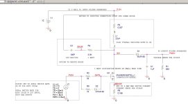
I'm studying how to achieve 40KHz PWM output from the UC3845.
- 1.72 / (21500 * 0.000000001) = 80kHz
- 1.72 / (1954 * 0.000000022) = 40kHz
Since duty cycle is 50% if I understand correctly the datasheet, the formula f = 1.72/(R x C) must give a freq 2x the freq required.
So the values should be 22K (possibly a bit lower) and 1nF.
Here the schematic I edited.
I went with ZEEWEII DSO2512G 2ch 120MHz 500Msps VIDEO OUTPUT with a basic Waveform Signal Generator."ZEEWEII-154Pro DSO154Pro 18MHz 40MS/s Digital Oscilloscope Signal Generator pe66"
And as a valid DMM this one, Zoyi ZT-225. 25000 counts, 20A, low error.
With this setup I should be able to cover my field needs as cheap as possible. And also portable, to work on live signal chains comfortably.
Tot. 110€
- Home
- Amplifiers
- Power Supplies
- 12V 555 based High Voltage power supply