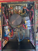
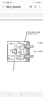
There are three on the so called LS-1 board. I will replace them.Impressive, yes!
I remember for the much smaller ML-9, and it was the first "big" amp I was touching.
I would recommend to check the two 672 Sprague on the DCO board. 680µF/6.3V on the ML-9, I guess not much different on the ML-3. If they're old, they are possibly crunched.
On the lower board, the SL-1 board there is one 6.8uF/50V axial that determines the switching delay as I gathered from one of your posts here.
You can see its top lead and top just above the toroid. Does an increase in capacitance gives the same increase in time? What I mean if you go from 6,8uF to 13,6uF the switching delay will go from let's say 0,8 to 1,6 seconds? The double stacked golden power-resistors will get hotter of course.
1. That's what I understand of the schematic. 2. On the other hand, I can't say what is the relation between the cap value and the delay time... As far as I can remember, I replaced the original 6.8µF with a 10µF and I didn't notice a large difference (if any) in the delay time. I think that wiser people around here can confirm (?) the point 1, and if so give their opinion about point 2... Question of time-constant I think.
I understand. 🙂Sorry, I don’t agree.
These caps can never conduct enough current to feed the amp, they are there to make the switch on of the diodes less abrupt.
Hans
More info for you from a VERY old thread: https://www.diyaudio.com/community/threads/dc-filter.2080/post-15973
Regarding the current, remember, the caps are on the primary side of the transformer and they must be selected for sufficiently high ripple current for the amp.
Yep. They are also in my ML3 but then in a enclosed resin filled box one per channel. You see both of them laying on one of the toroids.Regarding the current, remember, the caps are on the primary side of the transformer and they must be selected for sufficiently high ripple current for the amp.
MLAS started to implement these in 1982 in new ML2, ML3 and ML9 amps and could later be retrofitted.
They were called anti buzz circuit.

