As a thought, it seems this device (and the SSM2019) allows imposing the MC lines between the RG1 and RG2 pins and grounding the +IN and -IN connections. Of course this requires floating the cartridge leads. This creates a transimpedance input with feedback nulling applied by the two X1 buffers through the two 5K Ohm resistors, being equally applied to the difference amplifier via two more 5K Ohm resistors. Interestingly the reference pin supports a means of servo nulling the output to operate around zero (seemingly would already be close to this if grounded) . It should be noted that the low impedance of MC cartridges turns the network into a highish gain device with low noise. I'll have to try this when the SSM2019's arrive.
Last edited:

Thank you very much Hierfi for bringing this idea up. I was thinking the same but was afraid to be considered loony if bring it up . Mad as it is , It could work , exciting!As a thought, it seems this device (and the SSM2019) allows imposing the MC lines between the RG1 and RG2 pins and grounding the +IN and -IN connections. Of course this requires floating the cartridge leads. This creates a transimpedance input with feedback nulling applied by the two X1 buffers through the two 5K Ohm resistors, being equally applied to the difference amplifier via two more 5K Ohm resistors. Interestingly the reference pin supports a means of servo nulling the output to operate around zero (seemingly would already be close to this if grounded) . It should be noted that the low impedance of MC cartridges turns the network into a highish gain device with low noise. I'll have to try this when the SSM2019's arrive.
I noticed this form of connection is shown on page 8 of the SSM2019 data sheets so this isn't loony to the manufacturer. Though there is no requirement for the convoluted connections they show if you float the MC cartridge leads, allowing the normal input pins 2 and 3 to be directly grounded or through some low value resistances of perhaps 5-10 Ohms for some RF frequency suppression/stability purposes. Note too that the network is exceptionally well balanced with both halves of the input having equal impedances. This is good for RF suppression.
Bear in mind that this shorts the cartridge out, that with feedback it presents a near zero resistance input impedance that doesn't necessarily work well with all cartridges. It so happens that I believe Hans mentioned somewhere that the Denon 103R works with this form of shorted connection as the current trend in MC phono preamplifiers. For this reason I too am interested in trying it.
Bear in mind that this shorts the cartridge out, that with feedback it presents a near zero resistance input impedance that doesn't necessarily work well with all cartridges. It so happens that I believe Hans mentioned somewhere that the Denon 103R works with this form of shorted connection as the current trend in MC phono preamplifiers. For this reason I too am interested in trying it.
Last edited:
Hi, just short update, Figured noise measurements will be pointless without good chassis, so I made one. Good inspiration was also Dicks website http://www.dicks-website.eu/low_noise_amp_part1/part1.html, Also cleaned 2 old SSM2017 out of drawer and bought 2 ZTX951, ready for more playing.
PS, there is one and only one aspect where RCA is better than XLR, and that is when you make holes for XLR by hand. I think I could drill 50 RCA holes while making one XLR opening.


PS, there is one and only one aspect where RCA is better than XLR, and that is when you make holes for XLR by hand. I think I could drill 50 RCA holes while making one XLR opening.
Hi, I have seen it, I know that datasheet almost by hearth, but never consider so low impedance adequate. A week ago I would call myself loony if I proposed to short the cartridge.... now in course of this chat I learned it is very much ok. So thanks again for all who pointed that out.I noticed this form of connection is shown on page 8 of the SSM2019 data sheets so this isn't loony to the manufacturer.
That is a well-known configuration of the SSM2017/19 or THAT1510/12 as a console summing amp. It isn't loony at all.View attachment 1335395
As a thought, it seems this device (and the SSM2019) allows imposing the MC lines between the RG1 and RG2 pins and grounding the +IN and -IN connections. Of course this requires floating the cartridge leads. This creates a transimpedance input with feedback nulling applied by the two X1 buffers through the two 5K Ohm resistors, being equally applied to the difference amplifier via two more 5K Ohm resistors. Interestingly the reference pin supports a means of servo nulling the output to operate around zero (seemingly would already be close to this if grounded) . It should be noted that the low impedance of MC cartridges turns the network into a highish gain device with low noise. I'll have to try this when the SSM2019's arrive.
If the bases are grounded and the cart connected as Rg for a trans-impedance input, the common mode voltage at the emitters will be -Vbe. If one side of the cart were accidentally grounded there could potentially be large, destructive current flow through the coil.
It's better to bias the bases up one Vbe so the emitters are at ground. ADI show a common mode servo in the following circuit fragment. As shown R2 imbalances the CM impedance so it might be better if there was an additional R2' of the same value connected to the + input and also feeding the inverting input of the servo. A bias diode can also be used in lieu of a servo.
To correct differential offset the reference pin can be used to pin the output to 0V with a servo, but it cannot be used to sense common mode voltages at the emitters because they are rejected by the output differential amp.
Unfortunately there is no way to control the gain as the internal feedback resistors, 5KΩ, are fixed. Though it's a current input the gain can be approximated as 1+(Rfa+Rfb/Rgen). So for 5K feedback resistors and a 30Ω cart one should expect a gain of around 50 dB. With internal resistors gain is controlled solely by the cart's source impedance, Rgen.

SSM2017 Summing Amplifier
When you look at each half-circuit of the input differential amplifier with current injected into the emitter you may recognize that it is a common base topology with current feedback. 7-3(a) is the common base configuration while 7-3(b) is the more commonly-seen common emitter Demrow/Cohen topology.
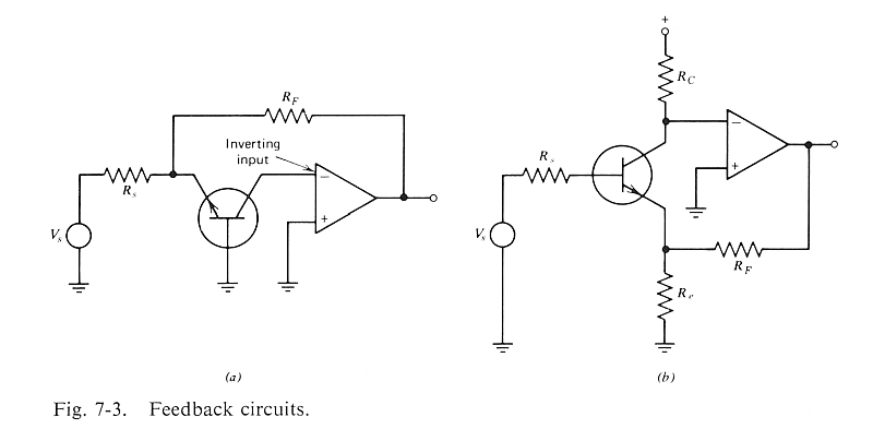
Motchenbacher and Fitchen Low Noise Design
Last edited:
"If the bases are grounded and the cart connected as Rg for a trans-impedance input, the common mode voltage at the emitters will be -Vbe. If one side of the cart were accidentally grounded there could potentially be large, destructive current flow through the coil."
"It's better to bias the bases up one Vbe so the emitters are at ground."
DC coupling $500+ MC cartridges to some experimental circuit is not for the faint of heart, notwithstanding how it is done. It bears emphasizing of the critical importance to verify the network is wired correctly before connecting a MC cartridge to it, as that too could cause catastrophic currents in the coils, notwithstanding a cartridge being inadvertently grounded in a network properly constructed.
It isn't clear if a network normally operating with summing inputs at -0.6 volts is necessarily any less safe. Grounding the -ve summing input would also result in shorting the inputs of A2 together causing it to open loop the bases the SS to a rail. This seems more problematic than terminating the bases directly to ground. It seems the diode network might be better, though this still may cause a drastic shift in the feedback mechanism.
My own plan is to solder up the SSM device on a vero-board and test what voltage drop occurs across a 15 Ohm resistor (in place of the Denon 103r having 14 Ohms) when one end of the ends is grounded as shifting from-0.6 V. It is expected the current will not exceed the emitter operating current of one of the input transistors modified by +/- V supply/ 5K Ohm. In considering the network the peak feedback current appears directly dependant upon the power supply voltage feeding into a 5K resistance, meaning that it may be safer to operate the SSM at perhaps +/- 5 Volts, limiting the maximum feedback current to 1mA.
The SSM's came in so I conducted some preliminary tests to determine expected MC fault currents (using a 15 Ohm resistor) if one end becomes shorted to ground from the 0.6V offset created by grounding the bases of the SSM2019 input devices . For +/- 15Volt supplies the voltage drop across the 15 Ohm resistor varied from 53mV to about 21mV dependent upon which end was shorted, corresponding to 3.5mA and 1.4mA respectively.
Using +8V/-8V or +15V/-8V supplies the voltage drop varied from 33mV to around 2mV corresponding to about 2.2mA and 0.15mA. As an aside, in both cases the difference current is about 2mA, suggesting that the input differential devices are operating at around 1mA constant current each.
In the literature it is suggested that the wire gauge of MC cartridges can vary anywhere from perhaps 42AWG to 56AWG. Although there is little trust in the accuracy of such a claim this suggests the fuse current of a MC cartridge can vary anywhere between perhaps 1mA and 15mA. From the results it seems doubtful that a cartridge such as the Denon 103R would be damaged by faults to ground, more so if the -ve supply was lowered to 8V or less.
Hi,
Tonight I found some time to go further with testing rig set up. To start I wired bellowed SSM2017 in new box just to establish how good the setup is.
I have no more PMI chips, so I used one "newer" AD variant.
This is circuit:

Assumptions and short cuts in above circuit:
a) Since in this test I used only one SSM, hence single output, I used old trick and made it balanced by equalizing output impedance's that sound card input will see. I should have reduced 75 OHM resistor at SSM2017 output for its output Z, but since that is not specified in datasheet, for the moment I imagine it is 0 Ohm.
b) As it is impossible to get source that will mimic cartridge, at least I tried to do as good as possible.
This is the picture of the set up (for measuring I removed instrument probes and lidded the chassis).
Left multi-meter is showing output AC voltage, right one input straight from sound-card before my attenuation H resistors. I had only resistors at hand to use, without complicating, still result not bad, 50db down, 50 db up. Foir the rest that I will show I kept strictly the same settings.

And one close up of the amp itself:

Tonight I found some time to go further with testing rig set up. To start I wired bellowed SSM2017 in new box just to establish how good the setup is.
I have no more PMI chips, so I used one "newer" AD variant.
This is circuit:
Assumptions and short cuts in above circuit:
a) Since in this test I used only one SSM, hence single output, I used old trick and made it balanced by equalizing output impedance's that sound card input will see. I should have reduced 75 OHM resistor at SSM2017 output for its output Z, but since that is not specified in datasheet, for the moment I imagine it is 0 Ohm.
b) As it is impossible to get source that will mimic cartridge, at least I tried to do as good as possible.
- Gain is set at 50db with 33R resistor (actually should be 32R, but I did not have one at hand). 50db was kind of democratically concluded as m,ax gain before EQ
- At input I created H network, again with 33R between chip inputs. Point was to attenuate input for amount close to gain of the chip, while keeping the impedance between input pins somewhere where more difficult (high Z ones) MC carts would be. ##ohm seems good both for gain and for mimicking chart, and makes my next step easier , don't need to exchange resistor when we move to testing current input variation.
This is the picture of the set up (for measuring I removed instrument probes and lidded the chassis).
Left multi-meter is showing output AC voltage, right one input straight from sound-card before my attenuation H resistors. I had only resistors at hand to use, without complicating, still result not bad, 50db down, 50 db up. Foir the rest that I will show I kept strictly the same settings.
And one close up of the amp itself:
And what did this circuit showed as measurement, as mentioned, with this I only want to establish test rig reference fop further work:

Well, one thing that one will not suffer from this chip is distortion, Seems it is at least one zero better than it is specified in datasheet.
The noise I got is -66db, in repeated measurements. I cant say how accurate is that. But when I will be testing different circuits I will use exactly the same setup, so at least we can see what is comparatively better or worse, without knowing absolute values.
On the square wave, please look and think many times before commenting its awful , please 🙂
Picture is scope on 2 channels but in opposite polarity. Yellow is closed loop soundcard, from out directly to in. This is how "good" square high end soundcard at 192/24 can produce.
Blue trace is the same signal reduced by 50db by resistors, and than amplified for 50db by SSM2017. I think it is perfect
While I have this setup installed (tomorrow I will dismantle it and move on) , I had to try something that I know but also needed to see for myself and to show to all differential signal routing skeptics, Surely I don't want to rub my believes in anyone's forehead, just to test and show what good signal routing does.
In any case, if you are at home with differential signal, please read no further. If in doubt, please read.
For this I used usual villain, 50Hz signal as most likely picked up as noise from trafo or mains.
The first measuring is when 50Hz is input as signal to this amplifier in differential mode (all same as diagram in # 151 above), all cool, amplified 304 times and into speakers. This is how signal is treated.
Second measuring is when the same signal (this time it is noise) is applied in common mode. When signal feeding cables are closely twisted together (as they should always be) and have the same impedance (as they should) , all the noises from environment are in common mode. This is a sketch of second measurement; input noise in common mode:

First, differential mode, aka signal, all as expected:

Second : common mode, so both legs get the same signal, 50HZ and very un-proportionaly large noise signal:

Please note there is nothing on the scope, the 50HZ common mode signal (aka external noise) is -80db ! That is CMRR with ad hook set up and one old SSM2017 properly wired,,,This is the merit of treating signal and return wires equally with proper differential input amp.
Nice evening,
Drazen
In any case, if you are at home with differential signal, please read no further. If in doubt, please read.
For this I used usual villain, 50Hz signal as most likely picked up as noise from trafo or mains.
The first measuring is when 50Hz is input as signal to this amplifier in differential mode (all same as diagram in # 151 above), all cool, amplified 304 times and into speakers. This is how signal is treated.
Second measuring is when the same signal (this time it is noise) is applied in common mode. When signal feeding cables are closely twisted together (as they should always be) and have the same impedance (as they should) , all the noises from environment are in common mode. This is a sketch of second measurement; input noise in common mode:
First, differential mode, aka signal, all as expected:
Second : common mode, so both legs get the same signal, 50HZ and very un-proportionaly large noise signal:
Please note there is nothing on the scope, the 50HZ common mode signal (aka external noise) is -80db ! That is CMRR with ad hook set up and one old SSM2017 properly wired,,,This is the merit of treating signal and return wires equally with proper differential input amp.
Nice evening,
Drazen
It might prove interesting to see what happens to the noise if you double the input transistor currents. It seems you are using 9Volt batteries. As a test you can do this by attaching a couple of 8K2 Ohm resistors from each end of the 33R Ohm gain setting resistor to the negative supply.
Good point, but for next day, its half past midnight here 😴It might prove interesting to see what happens to the noise if you double the input transistor currents. It seems you are using 9Volt batteries. As a test you can do this by attaching a couple of 8K2 Ohm resistors from each end of the 33R Ohm gain setting resistor to the negative supply.
Next 20 min test , this time with morning coffee.
Bias current for SSM2017 input LTP was roughly doubled by referencing 2 8k2 resistors to negative V-PS instead of ground.
I was not afraid for the chip as we use 1/3 of allowed PS voltage, and this variant is in really big form format.

All the settings on RME and REW being exactly the same as I did yesterday, the result is not going in expected direction:

The noise is similar (but worse for 1db), however THD is 54 times worse!?!? Even now the THD is much closer to datasheet 🤣
I cant explain above result but can say that engineers designing this chip got things right....
Next in the saga, I will try current (or bus summing) mode with attention on cart currents. Than one intervention of my own, then SSM2017 goes out of the box and I put discrete rig back in....
Bias current for SSM2017 input LTP was roughly doubled by referencing 2 8k2 resistors to negative V-PS instead of ground.
I was not afraid for the chip as we use 1/3 of allowed PS voltage, and this variant is in really big form format.
All the settings on RME and REW being exactly the same as I did yesterday, the result is not going in expected direction:
The noise is similar (but worse for 1db), however THD is 54 times worse!?!? Even now the THD is much closer to datasheet 🤣
I cant explain above result but can say that engineers designing this chip got things right....
Next in the saga, I will try current (or bus summing) mode with attention on cart currents. Than one intervention of my own, then SSM2017 goes out of the box and I put discrete rig back in....
Next test just done is in current mode, as Hierfi suggested and I was afraid to mention.
This is the wiring:

In above picture, 33R resistor connected to Rg pins of SSM2017 is kind of representing our cartridge. The signal is brought from soundcard via 2x 4k87 resistors, same as in previous set up.
I did not offset chip inputs, just grounded them.
First, I put probes across this 33R resistor to see how the cartridge is safe or not in this setup. One instrument was set to measure peaks in AC, other for peaks in DC. These are results:
It looks like that the cartridge is very safe in this setup, hard to believe any of above can damage the coil...
Next, I plugged the preamp into soundcard and generated signal. This is picture of one instrument measuring AC at input (Rg pins) and other at output:

The output (right instrument) is exactly where it should be, "cart" Rg of 33 ohms again gives 50db gain.
Voltage across the chart (left instrument) is exactly 0 volts, to confirm it is pure current mode.
Question, if voltage across 33R is zero, than also the current through it is zero. Can someone with more knowledge pls explain?
This is also confirmed by scope; blue is output, green is input V:

And the measurement is this:

Now this is becoming extremely interesting!
The noise went down just marginally, possibly I reached limitations of my measurement set up... Resistors deliverying signal are very high after all.
But THD went for another decade down ! I would never expect 0.00056% for amplifier with gain of 50db!!! This is so much better than what AD specified....
This is the wiring:
In above picture, 33R resistor connected to Rg pins of SSM2017 is kind of representing our cartridge. The signal is brought from soundcard via 2x 4k87 resistors, same as in previous set up.
I did not offset chip inputs, just grounded them.
First, I put probes across this 33R resistor to see how the cartridge is safe or not in this setup. One instrument was set to measure peaks in AC, other for peaks in DC. These are results:
- DC offset across the cart (33R resistor) : 0.15 mV
- DC between inputs and ground is 0,560 V at one input and 0.561 V at another, as expected.
- Peak when one PS (9V battery) is disconnected on the fly : 13mV AC and 20mV DC
- Peaks when other battery is disconnected: 17mV AC and 28mV DC
It looks like that the cartridge is very safe in this setup, hard to believe any of above can damage the coil...
Next, I plugged the preamp into soundcard and generated signal. This is picture of one instrument measuring AC at input (Rg pins) and other at output:
The output (right instrument) is exactly where it should be, "cart" Rg of 33 ohms again gives 50db gain.
Voltage across the chart (left instrument) is exactly 0 volts, to confirm it is pure current mode.
Question, if voltage across 33R is zero, than also the current through it is zero. Can someone with more knowledge pls explain?
This is also confirmed by scope; blue is output, green is input V:
And the measurement is this:
Now this is becoming extremely interesting!
The noise went down just marginally, possibly I reached limitations of my measurement set up... Resistors deliverying signal are very high after all.
But THD went for another decade down ! I would never expect 0.00056% for amplifier with gain of 50db!!! This is so much better than what AD specified....
Nice... though it would still be interesting to see what happens with doubling the input current in this configuration as well. It isn't clear if you may be clipping or approaching clipping in the first test. Remember that 50dB is 300x, for a 0.4mV cartridge, hence the output will be around 120mV. Using 1 volt RMS test signals may not be realistic in most circumstances.
In retrospect it may be better to use perhaps 200 Ohms resistors between the emitters (this would put another 400 Ohms across the coil winding) and use maybe 3.9K Ohm resistor from the center of these two to the negative rail. This will help with common mode rejection of noise in these resistors as well.
By the way I also tried shifting the base voltages using the diode arrangement shown in the SSM2019 data-sheet with result emitter voltages reducing to about 50mV. As expected shorting the one winding to ground didn't change the short circuit to ground, still at about 3mA with a 15Volt supply. Seemingly would be perhaps 2.5mA with 9Volt supplies.
"Resistors delivering signal are very high after all." Bear in mind that when the bases are grounded the high value resistors you add are now in parallel with the base/emitter junction as far as the network behaviour is concerned. This dramatically alters the nature of the circuit becoming ground referenced to a low impedance point to the split batteries.
Last edited:
Sure, I was interested too 🙂 .Nice... though it would still be interesting to see what happens with doubling the input current in this configuration as well. It isn't clear if you may be clipping or approaching clipping in the first test. Remember that 50dB is 300x, for a 0.4mV cartridge, hence the output will be around 120mV. Using 1 volt RMS test signals may not be realistic in most circumstances.
I'm sure it wasn't clipping, I was following the scope too all the time. Besides, H resistor network attenuates signal from sound card for about 50db, than amp brings it back to the same level again. I centered it around 1V for convenience. What amp input sees is 1V /314 roughly...
Ill most likely try that, but it will take few days, I have something else in mind 🙂In retrospect it may be better to use perhaps 200 Ohms resistors between the emitters (this would put another 400 Ohms across the coil winding) and use maybe 3.9K Ohm resistor from the center of these two to the negative rail. This will help with common mode rejection of noise in these resistors as well.
Agree. This circuit I made is just for testing, figured that DC offset will not alter AC performance. If circuit is choose, correcting offset is easiest thing to do at the end.By the way I also tried shifting the base voltages using the diode arrangement shown in the SSM2019 data-sheet with result emitter voltages reducing to about 50mV
I am into way to understand this, but still not there. 😵 Rin is shorted to ground (more precisely, between batteries), yes, but signal is still dropped over large R"Resistors delivering signal are very high after all." Bear in mind that when the bases are grounded the high value resistors you add are now in parallel with the base/emitter junction as far as the network behavior is concerned. This dramatically alters the nature of the circuit becoming ground referenced to a low impedance point to the split batteries.
- Home
- Source & Line
- Analogue Source
- Fully balanced MC phono preamplifier thoughts