He simulated Seas U22 which has very simular specs to the Scanspeak P21 and it simulated very nice.
Seas U22 Scanspeak P21
FS 28 29
VAS 103 113
QTS 0,29 0,33
I have Seas CA22RNX and Scanspeak D2608 laying around and have simulated a crossover for them. Maybe I should try that in the MLTL 10's first before modyfing the cabinets for dual SB Acoustics woofers.
Seas U22 Scanspeak P21
FS 28 29
VAS 103 113
QTS 0,29 0,33
I have Seas CA22RNX and Scanspeak D2608 laying around and have simulated a crossover for them. Maybe I should try that in the MLTL 10's first before modyfing the cabinets for dual SB Acoustics woofers.
Last edited:
By locating the woofer away from the closed end, that segment of the TL is effectively doubled i.e. the sound goes down to the closed end, and then reflects back out. Also, the progressive narrowing of the TL causes the air to progressively couple with the cone, and the added mass lowers the fundamental frequency of the speaker. I used Hornresp to do the 3D acoustic modeling; in conjunction with drawing the cabinet is DataCAD.Ideal line length is too short (1/4 WL) or too long (1/8 WL) based on a 28 Hz Fs = ~13543/4/28 = ~121", ~13543/2/28 = ~60.5", though fine tuning the vent solves this type of 'problem', but this means maybe enlarging it, so might want to try 'critically' damping it.
Because the TL is open at one end, it doesn't develop nearly as much air pressure - the air actually moves back and forth in the folded "column". So it doesn't flex the panels nearly as much. I used Baltic birch to build this speaker. The brace in the closed end is where some air pressure does develop, so the brace is where it is most needed.I would not be surprised if that is caused by panel resonances. According to the drawing the back panel is not braced at all. And the MDF structure does not do much. MDF is dense cardboard but it does not have any structural strength.
It has a Radio Shack made Linaeum dipole tweeter on the top of the cabinet.

This was only my second MLTL design. After this speaker, I have been using a nominal 6" paper cone SB Acoustics midwoofer, and I have a MLTL-6 standmount speaker that has a fundamental frequency of 32Hz, and a Tower 6 that has a FF of 25Hz. And I will be building a slightly speaker I am calling the Super Tower that uses a 6" Satori driver, that has a FF of 20Hz.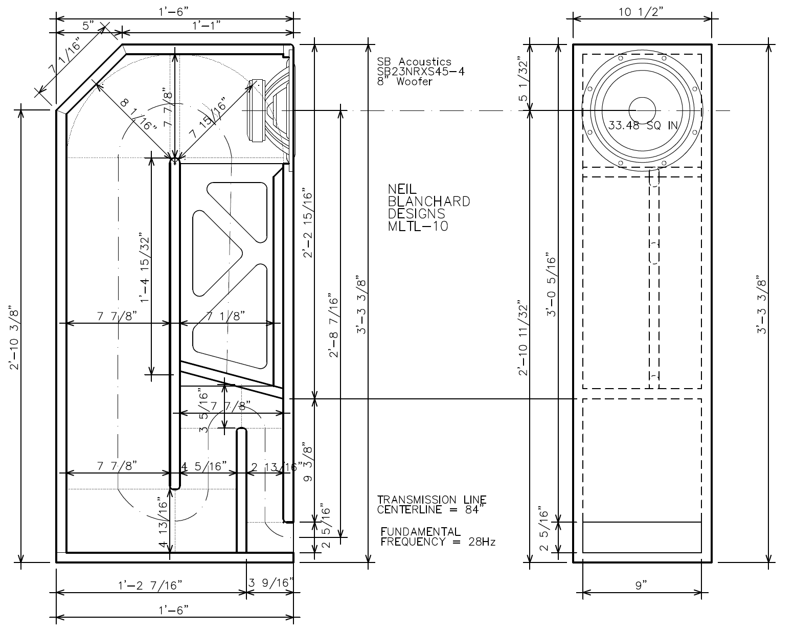
The deflector at t e back top is counterproductive.
dave
Hi guys, I have no idea about T-lines especially one called 1/4 or this case Peter Comeau calls it "Twin Drive TL Technology" on these small 3 way book shelves.
Can any of you say the effect it will have on this measured FR/efficiency/impedance & phase graph I found on them if I sealed up the TL line.
https://tinyurl.com/24yroz6k
The reason is I have 2 x 600mm high 210mm wide, very good servo controlled subs that will double as their stands
Cheers George
Can any of you say the effect it will have on this measured FR/efficiency/impedance & phase graph I found on them if I sealed up the TL line.
https://tinyurl.com/24yroz6k
The reason is I have 2 x 600mm high 210mm wide, very good servo controlled subs that will double as their stands
Cheers George
Attachments

2017-09-29-TST-Castle-Avon-2-m1.png
87.4 KB · Views: 5
Last edited:
The Avon 2 doesn't actually use what Castle call a 'Twin Drive TL' -if you look at the manual, it's actually what they describe as a 'Single Drive Extended Line'.
Translating: 'Twin Drive TL' as Dave says is simply a TL driven at two different locations by a pair of LF units (the idea, which isn't a new one, but rarely seen in commercial speakers except incidentally, being to even out the pipe harmonics. 'Single Drive Extended Line' is essentially just a marketing term for 'transmission line'. Which isn't meant negatively, since the measurements linked above show it's another of Peter Comeau's typically excellent designs. As for sealing it up -I wouldn't, but if you must, you'll likely find the LF impedance peak shifts up in Q and frequency -how much though I've no idea as it depends on the LF driver characteristics & how well you seal the box up. You'll probably find the FR similar, perhaps with some loss in output, as from the two graphs it already appears to be approaching an optimally damped TL of the classical Bailey / IMF / Radford / Augspurger type.
Translating: 'Twin Drive TL' as Dave says is simply a TL driven at two different locations by a pair of LF units (the idea, which isn't a new one, but rarely seen in commercial speakers except incidentally, being to even out the pipe harmonics. 'Single Drive Extended Line' is essentially just a marketing term for 'transmission line'. Which isn't meant negatively, since the measurements linked above show it's another of Peter Comeau's typically excellent designs. As for sealing it up -I wouldn't, but if you must, you'll likely find the LF impedance peak shifts up in Q and frequency -how much though I've no idea as it depends on the LF driver characteristics & how well you seal the box up. You'll probably find the FR similar, perhaps with some loss in output, as from the two graphs it already appears to be approaching an optimally damped TL of the classical Bailey / IMF / Radford / Augspurger type.
Bailey's re-imagination and advice in 1972 and Sanders interpretation and construction tips in his Audio Amateur article on an electrostatic-based system were useful if one was intent on building such a system.
Still wonder what will happen if I did this, if anyone knows?
https://www.diyaudio.com/community/...ansmission-line-alignment.243483/post-7740885
Cheers George
https://www.diyaudio.com/community/...ansmission-line-alignment.243483/post-7740885
Cheers George
You can see the ripple andit doesn’t go very low,

But the impedance suggests it is heavily damped.

What driver(s)?
On first look, it could use some work.
dave
But the impedance suggests it is heavily damped.
What driver(s)?
On first look, it could use some work.
dave
Without stripping them down Dave this is all I have https://www.hifi-voice.com/testy-a-recenze/reprosoustavy-regalove/1491-castle-avon-2What driver(s)?
And I know the ribbon is the Fountek Neo1.0
Cheers George
PS: Is that ripple a TL characteristic? Also the horizontal scale is 5db graduations so it looks worse than it would at normal graph 10db graduations.You can see the ripple
Also Dave looking at that FR graph (if it's correct) at what frequency would you think to bring in subs that have a 3rd order active xover.
Cheers George
Last edited:
See my reply above.Still wonder what will happen if I did this, if anyone knows?
https://www.diyaudio.com/community/...ansmission-line-alignment.243483/post-7740885
Cheers George
you'll likely find the LF impedance peak shifts up in Q and frequency -how much though
Thanks Scott missed your post, but what "could" that translate to what's heard?
As I can afford to loose some lf extension because the double 8"servo 2 x subs are well capable to take over up to even 150hz if needed, but I can't loose any efficiency above say 100hz, if anything be nice if it bumped the 150mm bass drivers efficiency up a touch.
Cheers George
Last edited:
looking at that FR graph (if it's correct) at what frequency would you think to bring in subs that have a 3rd order active xover.
If i was doing that i would add damping to work to kill the ripplw from the unwanted TL harmonics and smooth the way iy rolls off at the bottom.
The natural rolloff will be 4th order althou if pushed aperiodic it starts out slow. Factor that into your XO.
Are those emasures yours?Or someone posting on ASR?
dave
They are the measurements taken from a review from a Czech site call HiFi-Voice, by the "editor in Chief" Daniel Brezina.Are those emasures yours?Or someone posting on ASR?
https://www.hifi-voice.com/testy-a-recenze/reprosoustavy-regalove/1491-castle-avon-2
Cheers George
Not so, shifting the driver down just alters the pipe's harmonic structure and your tapering has such a high reduction in taper to qualify as an inverse cone vent, hence the low tuning, but in retrospect, don't recall my 'knee jerk' response being WRT your design, so my bad for not attaching some sort of reference.By locating the woofer away from the closed end, that segment of the TL is effectively doubled i.e. the sound goes down to the closed end, and then reflects back out. Also, the progressive narrowing of the TL causes the air to progressively couple with the cone, and the added mass lowers the fundamental frequency of the speaker. I used Hornresp to do the 3D acoustic modeling; in conjunction with drawing the cabinet is DataCAD.


Nice design, execution BTW. 😎
See my reply above 😉Thanks Scott missed your post, but what "could" that translate to what's heard?
i.e. not dissimilar, just rolling off at a higher frequency.You'll probably find the FR similar, perhaps with some loss in output, as from the two graphs it already appears to be approaching an optimally damped TL of the classical Bailey / IMF / Radford / Augspurger type.
Last edited:
- Home
- Loudspeakers
- Full Range
- An Improved Transmission Line Alignment