Hi there, i was inspired by Nola brios since i have two TG9 4 ohm, and i came out with this.
With my limited understanding, it seems the phase shift an aperiodic TL provides helps create a cancelation over a wide band.
In this case, the TL is tuned so there is a 360° phase difference at approx 650 Hz, and below that, until port tuning freq (200 Hz), i get a nice rear wave cancelation. This was choosed as an 3.5 inch driver is expected to abandom omni pattern arround there. For some reason, the OB makes for a better cancelation (in vituixcad), if its inverted, as prob brios are, according to some measurments in the brio thread.
Vituixcad shows awesome cancelation, but little arround TL tuning f, AKABAK shows the opposite.
Some sim images to show what i'm talking about...
The akabak sim is for generic speaker, no LEM data inserted as of now. TL was simed using Leonard audio and then translated to the other programs.
Now that both programs are showing the effect i'm after, i'll make some more iterations on akabak, and i'm gonna build it soon-
recomendations welcomed! Best regards!


This one is an imposible thing, as port distance from front baffle is about double of the TL, but it shows the effect real nice. I also ended up making distance between drivers 220 mm as 364 mm seemed like too much visually. Also, it makes the dip at 8Khz way more benign. The idea is that some day far from now, some supertweeter will lay there.
(forget the cap its not doing anything) (i will waste some power to make the load 4 ohm)
I bet this speakers from project10 are pretty directional too: https://www.diyaudio.com/community/threads/aperiodic-loading-to-lower-qt.162130/
With my limited understanding, it seems the phase shift an aperiodic TL provides helps create a cancelation over a wide band.
In this case, the TL is tuned so there is a 360° phase difference at approx 650 Hz, and below that, until port tuning freq (200 Hz), i get a nice rear wave cancelation. This was choosed as an 3.5 inch driver is expected to abandom omni pattern arround there. For some reason, the OB makes for a better cancelation (in vituixcad), if its inverted, as prob brios are, according to some measurments in the brio thread.
Vituixcad shows awesome cancelation, but little arround TL tuning f, AKABAK shows the opposite.
Some sim images to show what i'm talking about...
The akabak sim is for generic speaker, no LEM data inserted as of now. TL was simed using Leonard audio and then translated to the other programs.
Now that both programs are showing the effect i'm after, i'll make some more iterations on akabak, and i'm gonna build it soon-
recomendations welcomed! Best regards!
This one is an imposible thing, as port distance from front baffle is about double of the TL, but it shows the effect real nice. I also ended up making distance between drivers 220 mm as 364 mm seemed like too much visually. Also, it makes the dip at 8Khz way more benign. The idea is that some day far from now, some supertweeter will lay there.
(forget the cap its not doing anything) (i will waste some power to make the load 4 ohm)
I bet this speakers from project10 are pretty directional too: https://www.diyaudio.com/community/threads/aperiodic-loading-to-lower-qt.162130/
Last edited:
Ended up opting for a double 30° driver offset folded OB. This makes acoustic centers closer, makes the breakup peaks arround 9-11 Khz add a little more to dispersion and a little less to the peak. Opted for a PTmini as super tweeter, as its real cheap...
Made some crossovers trying to avoid a notch for cone breakup, anyway u ended up having to make two coils...
I have some more efficient crossovers, but,
Would a 1.5 Ohm impedance dip arround 20kHz couple something dangerous or some EMI?
I'm guessing the amp should't oscillate this low, if working properly... And if it happened, it would be audible, right?
I attach the one with a dip of 2.2 Ohm. Response of both drivers and super tweeter at 0° 20° and 40°
With the design of an aperiodic TL, things largely simplify down to a box large enuff to contain suffieict damping so that there is no output at the terminus. It is very hard to achieve completely.
I’m not sure that any modeler yet have the necessayr data on heavy use of damping material to do a decent sim.
GM’s clik test or an impedance measuring jig will rpovide more information on the state of tune.
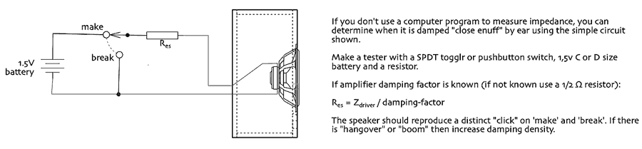
dave
I’m not sure that any modeler yet have the necessayr data on heavy use of damping material to do a decent sim.
GM’s clik test or an impedance measuring jig will rpovide more information on the state of tune.
dave

Wonderfull test, makes for an situation too!
what was used in the sim was the phase output from TLine software from LA, along with port output. Seems like apeeriodish in the way there is ONE peak.
Full aperiodics (with some random stuffing density at the program), meaning no peak, did't affect directivity in the 200-1000HZ as much, for my sims.
apeeriodish in the way there is ONE peak
If it was perfect there would be no impedance peak at all. VERY hard to achieve.
Here is the impedance of one our “aperiodic”midTLs vrs free air.
dve
What does the phase look like? It's helpful to attach an impedance plot with magnitude and phase when asking a question like this.a 1.5 Ohm impedance dip arround 20kHz couple something dangerous or some EMI?
I'm guessing the amp should't oscillate this low, if working properly... And if it happened, it would be audible, right?
Some idea about the amplifier would help also. If it's something like a Krell, I'd say you're fine. If it's a home theater receiver, less so.
An impedance that low can cause problems with some amplifiers, and more so if impedance is low and the phase angle is capacitive at high frequencies (phase margin issues).
No, oscillations are not always audible. Minor ones may just have overshoot and ringing riding on top of the signal, but sound reasonably OK. Driving the system with a square wave and observing the amplifier output on an oscilloscope will highlight issues like this. More serious oscillations may consume a bunch of power and increase distortion. If they have the circuitry, some amps will go into protection when pushed hard with a difficult load.
Ok, i could potentially run a square test... Currently i'm using two crica 2005 sony amplifiers, one home audio and other home theater (both spec 6 Ohm output), so i should be cautious then. I will make a circlophone with a 18V-0-18v transformer that will be its actual amp if it works.
For example for this crossover there is also a 1.8 ohm dip, it seems more problematic, as the filter is less selective and compromises the impedance into the 50Khz range.
I would have to use spice to see the impedance above 40Khz, but i believe there is always a series inductor that ll determine phase hi up, may be wrong.
Last edited:
You may be able to include more series resistance to bring the impedance up for initial tests. If you raise your 1 ohm resistor to something like 4 ohms, the amp should be happier. It'll waste some power, but if the amp is unhappy without it, still might be a net positive.
Also, your inductor values in the tweeter circuit look odd (small). My simulator is on a different computer, so I can't run through your circuit at the moment to see what you have going on there.
And the circuit has changed since earlier posts. Did you mean to switch to a series configuration or was that a layout error? I normally try to lay out my simulations like the textbook circuits to help keep things straight. Some people seem to like the plate full of spaghetti approach though 🙂
The parallel versions usually ended up loosing up too much high freq if rasing series resistance, so i ended up with that madness.
If you saw some not posted iterations it would seem like a modern art vituix thingy 😊.
This other version seems to tolerate series resistance better, using 4 ohm series resistance i can't optimize better than less 1-2dB at 18Khz, pretty marginal. I may live with something like 2.7, 3.3 .
There is one interesting thing about the circuit, the value of the resistor parallel to the inductor is sort of a volume controle for the tweeter. While it rises, it's also a notch filter that helps drivers bend as it lowers breakup at 11Khz.
Below is almost same crossover, 0 Ohm, and 220 mOhm for such resistor
Series crossovers tend to get complicated if the drivers need much response shaping. The interactions aren't as intuitive or predictable as those in parallel configurations.
It's also more important to try them in the real world to see what you actually have. Some of my series attempts never really did what my simulations predicted. With enough work they would usually get close, but there was always a lot more trial and error with actual parts than a parallel circuit would have needed.
I wouldn't be too worried about the high frequency roll-off at the moment. Plenty of very nice speakers don't maintain their output to 20 kHz, and most people don't notice. If your tests are more about the configuration, I would focus on that and grab whatever simplification I could get. You can always add complexity later.
Today i'll cut the wood at the workshop. The goal after deciding for the OB is to add a supertweeter to have more dispersion and output above 14khz. Max two inductors as low as possible, using two 4.7 uF mkt i have arround.
I guess i won't skip the masurment part then... My calibrated mic is gone but i Guess i can still compare levels reliably.
Best regards!
I guess i won't skip the masurment part then... My calibrated mic is gone but i Guess i can still compare levels reliably.
Best regards!
- Home
- Loudspeakers
- Full Range
- The Aperdioid - ish