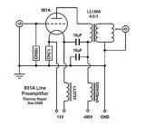
will be nice with a good trafo step downThe project with 6C4C is for the guy who has a EAR amp with approx. 10K input impedance
5:1 15k:600 ohm or 10k:600 ohm
Walter
I'm sorry not, but I think are for different purpose.Merlin - do you have experience with Ale's Source Follower as an alternative to the mu-follower?
For information on using solid state devices to augment valves you might want to look at Merlin Blencowe's "Designing High Fidelity Tube Preamps" (book). I like how clear and easy to follow Merlin's prose is, and he concentrates on useful stuff all the way through. His Power Supplues book is also very useful.
Source followers are very easy to add to valves. Easily DC coupled too, as long you use a high voltage MOSFET.
Source followers are very easy to add to valves. Easily DC coupled too, as long you use a high voltage MOSFET.
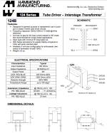
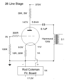
I may have another possible solution - add a Hammond 124b 90K/10K 3:1 stepdown on the end of the 26 preamp. This would be like a parafeed arrangement. I'm listening to it now. Sounds promising. The Hammond 124B is 49% nickel so good quality. Only question is whether it would overload. Data says 5 watts. Output impedance would be around 850 ohms so that's OK.will be nice with a good trafo step down
5:1 15k:600 ohm or 10k:600 ohm
Walter
What do you think?

The primary inductance is 65,38H. What would the secondary inductance be?
Probably a lot less than 65H.
Probably a lot less than 65H.
With a parafeed configuration, you're supposed to use a choke, a gyrator, or a CCS to load the triode's anode (plate), and you need to size the DC blocking capacitor to work with the transformer's primary inductance to avoid any undamped resonances and to make sure the output goes low enough in the bass. To do that you need to know the primary inductance of the OPT, but in this case you need to know the transformer's secondary inductance, because you're using the primary as the secondary.
Thanks - useful information. I haven't worked out the size of the coupling cap. Need to do more calculations.
But why are you supposed to use a choke, a gyrator, or a CCS to load the triode's anode? Why not a resistor?
But why are you supposed to use a choke, a gyrator, or a CCS to load the triode's anode? Why not a resistor?
Calculation of coupling cap value once plate choke inductance is known:
https://www.diyaudio.com/community/...e-and-transformer-values.384498/#post-6978123
From Lundahl site:
https://www.jacmusic.com/lundahl/html/plate.html#:~:text=With parafeed, the DC component,why plate chokes are used.
Explanation on bottlehead forum:
https://forum.bottlehead.com/index.php?topic=12168.0
I'm sure there's more on this elsewhere... I'll bet there's good info in the Radio Designer's Handbook 4th Ed. (!)
I've simulated stuff like this in LTspice, and found that using real-world components, the coupling cap usually needs to be a very large value, like 20uF or so. That makes things a bit more expensive, and some people will say SCR caps sound bad, etc etc etc.
Thanks, that's good to know!
So, if the impedance ratio is 10k:90k then the turns ratio is 1:3.
If Lpri and Lsec have the same ratio as the turns ratio, then Lsec is 65/3 = 21.67 Henries (about)
Let's round that off to 22H. That's not a lot of inductance. To get to -3dB at 15Hz, you'd need the coupling cap to be at least 5uF. For -3dB at 10Hz, C would need to be at least 11.5uF.
We also want to remember that the coupling cap and primary inductance form a series resonance, damped by the resistive parts of impedance at the output valve's anode, often not a lot. Q is calculated in the usual way, X-sub-L (=X-sub-C at resonance) / that resistive part.
If the Q is below maybe about 1.0 this issue can be ignored, but that's not often the case.
(Resistive part can be estimated as a parallel of reflected load resistance and anode dynamic resistance r-sub-p.)
All good fortune,
Chris
If the Q is below maybe about 1.0 this issue can be ignored, but that's not often the case.
(Resistive part can be estimated as a parallel of reflected load resistance and anode dynamic resistance r-sub-p.)
All good fortune,
Chris
This is a great tool by Gianluca and Dave Slagle! Includes parafeed stage.
https://forum.intactaudio.com/viewtopic.php?f=15&t=316

https://forum.intactaudio.com/viewtopic.php?f=15&t=316
Last edited:
what I see that this stuff hasn't a very good freq. response as described.Hammond 124b 90K/10K 3:1 stepdown on the end of the 26 preamp
So maybe the final solution, even it can be fine as gain, impedance .etc, will be not with a good level.
In addition the use of parafeed is something like a secondary way to get some results.
And the use of a inductive load then the parafeed is a wrong way to fix a circuit; there are four non linear components, three coils and one cap (plus tube of course)
While with only one trafo 5:1 on anode the solution, even not cheap, will be fine
My opinion
Walter
I used this oneYes, Walter, that's what I was thinking
https://www.sowter.co.uk/specs/1160.html
good and not so expensive
or 9041
https://www.sowter.co.uk/specs/9041.htm
Walter
Primary inductance refers to the 10k impedance. Since the transformer is used as a step down (backwards), that means that the 90k impedance, used now as a primary winding, has an inductance of ca. 195 Hy.Thanks, that's good to know!
So, if the impedance ratio is 10k:90k then the turns ratio is 1:3.
If Lpri and Lsec have the same ratio as the turns ratio, then Lsec is 65/3 = 21.67 Henries (about)
Let's round that off to 22H. That's not a lot of inductance. To get to -3dB at 15Hz, you'd need the coupling cap to be at least 5uF. For -3dB at 10Hz, C would need to be at least 11.5uF.
- Home
- Amplifiers
- Tubes / Valves
- Low Rp tube for line stage - ideas?

