6S41S is better. More linear, better anode shape, but still opened a lot...
settings for high voltage like vacuum tub device i designed for. Lower THD
.

settings for high voltage like vacuum tub device i designed for. Lower THD
.
Code:
**********************************************
* Created on 06/12/2024 09:57 using paint_kit.jar 3.1
* www.dmitrynizh.com/tubeparams_image.htm
* Plate Curves image file: /Users/zoran/Desktop/Model_Paint_Tools/Graph/
* Data source link:
*----------------------------------------------------------------------------------
.SUBCKT 6S41S 1 2 3 ; Plate Grid Cathode
+ PARAMS: CCG=11.7P  CGP=15.7P CCP=6.7P RGI=2000
+ MU=2.62 KG1=1035 KP=14 KVB=14 VCT=0 EX=1.61
* Vp_MAX=480 Ip_MAX=320 Vg_step=10 Vg_start=20 Vg_count=25
* Rp=3000 Vg_ac=3 P_max=25 Vg_qui=-110 Vp_qui=265
* X_MIN=51 Y_MIN=25 X_SIZE=986 Y_SIZE=652 FSZ_X=1832 FSZ_Y=759 XYGrid=true
* showLoadLine=y showIp=y isDHT=n isPP=n isAsymPP=n showDissipLimit=y
* showIg1=n gridLevel2=n isInputSnapped=n
* XYProjections=y harmonicPlot=y dissipPlot=y
*----------------------------------------------------------------------------------
E1 7 0 VALUE={V(1,3)/KP*LOG(1+EXP(KP*(1/MU+(VCT+V(2,3))/SQRT(KVB+V(1,3)*V(1,3)))))}
RE1 7 0 1G  ; TO AVOID FLOATING NODES
G1 1 3 VALUE={(PWR(V(7),EX)+PWRS(V(7),EX))/KG1}
RCP 1 3 1G   ; TO AVOID FLOATING NODES
C1 2 3 {CCG} ; CATHODE-GRID
C2 2 1 {CGP} ; GRID=PLATE
C3 1 3 {CCP} ; CATHODE-PLATE
D3 5 3 DX ; POSITIVE GRID CURRENT
R1 2 5 {RGI} ; POSITIVE GRID CURRENT
.MODEL DX D(IS=1N RS=1 CJO=10PF TT=1N)
.ENDS 6S41S
*$
It's not the Leak power supply - I built a new one. The choke is rated 40mA but it's pretty small. Also it's resistor loaded and I like larger anode resistors. I could take it up closer to 15mA maybe.Hey Andy! Looks like a fun project! Can you explain why you’re running the 6ah4 with only 10ma? Dave
Speaking of lower currents through tubes, I was running the 6C4C at 13mA and getting a very clean and detailed sound out of it, though not a very "full" sound. So I did the obvious and tried it at 17mA. To my surprise it sounded worse - less detail and not so clean. So I tried it at 15mA and that seemed to work OK, and better than 16mA. I don't know what's going on here - can anyone guess why a tube should sound good at a low current?
It just occurred to me that when you run the triode at lower plate currents, its gm will go down (but mu stays pretty much the same), which means its rp will go up. That means its Zout will go up as plate current goes down.
The data sheet rp for 2A3 (and 6B4G) is 800 ohms, but that's at the more usual operating conditions for use as a power output tube. I'd imagine that with 13mA Ip the rp would go up over 1k ohms. Wouldn't that change the sound into a load?
BTW, what is the load? Way high like 220k ohms or more? Or down around 50k ohms?
It's destined to drive a EAR 861 push-pull amp. Odd to have a 10K input impedance, and I can't see why an ECC83 is the first valve - all that gain with a quoted "zero feedback" amp?
I've settled on 15mA for now - sounding very nice. So nice I'll have to build another for myself.

I've settled on 15mA for now - sounding very nice. So nice I'll have to build another for myself.
10k ohm input impedance?
From its schematic, it looks like the EAR 861 has balanced inputs.
http://www.troelsgravesen.dk/EAR-861/schematics.png
Is the 6S4S driving an output transformer with balanced output?
If its Zout isn't too high, and considering that a 6B4G/6S4S makes a good line stage, wouldn't a 45 do even better?
From its schematic, it looks like the EAR 861 has balanced inputs.
http://www.troelsgravesen.dk/EAR-861/schematics.png
Is the 6S4S driving an output transformer with balanced output?
If its Zout isn't too high, and considering that a 6B4G/6S4S makes a good line stage, wouldn't a 45 do even better?
EAR-861 has balanced first stage, but has XLR and RCA input too... and volume potentiometer.
Exact -factory- data of unbalanced input impedance is not available, some sources publish 10k, some 47k.
Exact -factory- data of unbalanced input impedance is not available, some sources publish 10k, some 47k.
10K measured on the RCA inputs.
I've started making my own 6C4C stage already. It's not quite loud enough for classical music, unfortunately, but just OK for jazz and popular stuff driving my EL12 type outputs. I'm wondering about an output transformer with a slight step up. Doesn't need much and on my system it goes into 470K so no issue there. Maybe a plate choke would give a tad more volume than a resistor load.
My 6C4C line stage as described is being picked up Sunday. I have a few spare valves, fortunately.
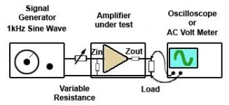
Measuring Input Impedance
The set up for measuring input impedance is illustrated in Fig. 7.3.1. A variable resistor or a decade resistance box is connected between the signal generator and the amplifier input and its resistance is set to zero Ohms. An oscilloscope or AC voltmeter is connected across the amplifier load (e.g. loudspeaker).The signal generator is set to provide a sine wave output at 1kHz. The amplitude of the input signal should be adjusted so that the display on the oscilloscope is noise free (large enough) and distortion free (not too large). The display on the oscilloscope screen should be as large as is practical and set so that its amplitude and half its amplitude can be easily estimated.
The resistance at the amplifier input should then be increased until the output waveform is exactly half its previously set value. At this setting the signal is shared equally between the test resistance and the input impedance of the amplifier, meaning that the resistance and impedance are equal. After switching off and removing the test resistance, the reading of the decade box settings or measuring the variable resistor with an Ohm meter gives the value equivalent to the input impedance of the amplifier.
Attachments
So it is true then, that their cathodes burn out quickly.Absolutely no! This has been tried out with fine hopes and....
- doesn't sound so good
- short cathode life and starts to distort badly
not as simple as that....Input & output impedance can't be measured with DVM.
TI handbook gave methods for testing...
Attachments
In Audioreview lab we use the method described by Merlin
We have a box with also a switch for capacity in pf
We use 100 hz for R and 10 kHz for input capacitance that it is important to know with tubes
Walter
We have a box with also a switch for capacity in pf
We use 100 hz for R and 10 kHz for input capacitance that it is important to know with tubes
Walter
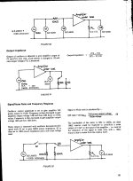
This is the freq answer with a full trafo line stage with 6H30, paralleled triode
Vdc 160 volt
Ia =27 mA
Input 10:10k mumetal
Out nano cryst. trafo 10k:600 ohm
Vin 1vac
Vout 5vac

The FFt at 1 Vout

Vdc 160 volt
Ia =27 mA
Input 10:10k mumetal
Out nano cryst. trafo 10k:600 ohm
Vin 1vac
Vout 5vac
The FFt at 1 Vout
If you measure 10K on the input it tells you the grid leak resistor is 10K, no?Input & output impedance can't be measured with DVM.
How far off that can the input impedance be on a simple valve gain stage?
Andy, impedance is a complex value that takes into account frequency, capacitances, inductances, resistance. Let's say you put a 1000pf capacitor in parallel with those 10K. A DMM will still show 10K, but the impedance value at audio frequencies will be lower, because you have two resistors in parallel, the real one and the capacitor one.If you measure 10K on the input it tells you the grid leak resistor is 10K, no?
The DMM uses DC, leaving the capacitor out of the equation, bar parasitic currents.
if it is good enough with Vac setting and good generator it is possible ro read the values; of course I read the output signal from circut checking first the inputThe DMM uses DC, leaving the capacitor out of the equation, bar parasitic currents.
With a Fluke, p.e., it is possible
Walter
If you measured 10k (with rolled down volume controller) it shows that potentiometer (before the capacitor coupled input of EAR861) has such resistance.If you measure 10K on the input it tells you the grid leak resistor is 10K, no?
It doesn't say anything about power amp input impedance.
"It doesn't say anything about power amp input impedance."
Yes, I get that. My question was "How far off that can the input impedance be on a simple valve gain stage?"
e.g. if the input resistor is 10K the impedance is unlikely to be 100K..........? What's a ballpark figure?
https://wtfamps.com/inputoutput-impedance/
The link states that for a grounded cathode stage Zin = Rg || Zmiller
Last edited:
- Home
- Amplifiers
- Tubes / Valves
- Low Rp tube for line stage - ideas?