I inputed 1500 (6 × 250), not 1000.
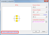
If Re = 3.6 ohms and loudspeaker driver configuration = 3P 2s then:
Loudspeaker dc input impedance = (2 * 3.6) / 3 = 2.4 ohms
(As shown in Attachments 1 and 2)
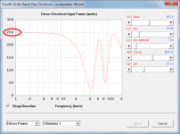
If Eg = 60 volts then:
Loudspeaker dc input power = 60 ^ 2 / 2.4 = 1500 watts
Driver dc input power = 1500 / 6 = 250 watts
(As shown in Attachment 3)
(1 hertz is close to dc)
Attachments
but only the chart Y-axis scale should be divided by 10.
The scaling factor is used to ensure that values displayed along the y-axis cannot exceed the available width.

David, I need your help with this one
From help file

Datasheet


So for parallel coils. Is this data entry correct?

Thanks and regards
Randy
From help file
Datasheet
So for parallel coils. Is this data entry correct?
Thanks and regards
Randy
If Re = 3.6 ohms and loudspeaker driver configuration = 3P 2s then:
Loudspeaker dc input impedance = (2 * 3.6) / 3 = 2.4 ohms
(As shown in Attachments 1 and 2)
If Eg = 60 volts then:
Loudspeaker dc input power = 60 ^ 2 / 2.4 = 1500 watts
Driver dc input power = 1500 / 6 = 250 watts
HR is stating 1000 watts when I input 1500 watts at 2.4 ohm with a Re of 3.6 ohm.
Power as an input?
Something only requires power.
In 99.8% of loudspeaker designs we have a voltage as input.
The only things you have to watch for:
The last one can only be seen from the VA graph.
Aka Eg^2/Z(f) (impedance)
Something only requires power.
In 99.8% of loudspeaker designs we have a voltage as input.
The only things you have to watch for:
- can de amplifier deliver the voltage (because of the danger of clipping)
- deliver the required power, or rather current
The last one can only be seen from the VA graph.
Aka Eg^2/Z(f) (impedance)
I used the Stepped Nd function to get more HR options than with the BP4 function.
Power went up to 2000 watts at 2.4 ohm with a Re of 3.6 ohm.
Rg + Re is showing 1330 watts.


BP4 function updated. The model was not refined when I asked the 2.4 vs 3.6 ohm question.
The difference in volumes is the 1.905cm (0.75in) speaker baffle (Vtc & Atc in the Stepped Nd model).


Power went up to 2000 watts at 2.4 ohm with a Re of 3.6 ohm.
Rg + Re is showing 1330 watts.
BP4 function updated. The model was not refined when I asked the 2.4 vs 3.6 ohm question.
The difference in volumes is the 1.905cm (0.75in) speaker baffle (Vtc & Atc in the Stepped Nd model).
60V is 450 watts into 8 ohms, 60v is 1kW into Re (3.6) as you highlighted in yellow.HR is stating 1000 watts when I input 1500 watts at 2.4 ohm with a Re of 3.6 ohm.
View attachment 1326820
Re = 3.6 ohms and your loudspeaker driver configuration is 3P 2s, so:
Loudspeaker dc input impedance = (2 * 3.6) / 3 = 2.4 ohms
As you say, 60v into 2.4 ohms is 1500watts, 1500 divided by 6=250 per driver..
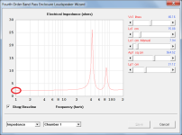
The combined driver impedance varies with frequency, so does the power.
And 69.28v into into 2.4 ohms is 1.33 kW.Power went up to 2000 watts at 2.4 ohm with a Re of 3.6 ohm.
Rg + Re is showing 1330 watts.
The DC resistance of 3P 2s is still 2.4 ohms.
69.28 into 2.4 ohms is 1999.88 watts. (2kW)
2000/6=333.3 watts per driver.
The combined driver impedance varies with frequency, so does the power.
Hornresp does the math using the driver configuration and the driver Re to calculate "Driver Electrical Input Power (watts)".
Nothing out of the ordinary in the "Driver Electrical Input Power (watts)" in your post #14827, or the previous posts 14,814 or 14,824.
Art
So for parallel coils. Is this data entry correct?
It depends on how the data on the driver specification sheet is to be interpreted. It says DC Resistance = 3.2 + 3.2 ohm. Does this mean that the parameter values apply to two coils connected in series, or to just a single coil?
HR is stating 1000 watts when I input 1500 watts at 2.4 ohm with a Re of 3.6 ohm.
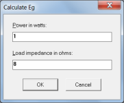
It is important to understand the difference between Re and load impedance. The powers will be the same if the loudspeaker has a single driver and the load impedance equals Re, but the powers will be different if the loudspeaker has multiple drivers and the load impedance does not equal Re, as is the case for your example.
The form shown attached is simply a stand-alone tool enabling the user to calculate the voltage necessary to deliver a given power into a given load. It is not related to the power message displayed in the status bar panel at the bottom of the Input Parameters window which refers to Re, not load impedance. As stated above, the only time that the powers will be the same is when the load specified in the form is equal to Re.
Please re-read my Posts #14,816 and #14,821 and think carefully about what they say. I have no desire to enter into another prolonged discussion with you, so this will be my final post on the matter.
Attachments
Mmmm... this is MIT Level HornResp Talk....
Not really, if you understand the difference between Re and load impedance in a multiple-driver loudspeaker 🙂.
The tech support replied that the specs are per coilIt depends on how the data on the driver specification sheet is to be interpreted. It says DC Resistance = 3.2 + 3.2 ohm. Does this mean that the parameter values apply to two coils connected in series, or to just a single coil?
The tech support replied that the specs are per coil
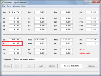
In that case there would appear to be something amiss with the Bl value given on the driver spec sheet. Using the Thiele-Small parameter values shown in Attachment 1, the Bl equivalent works out to be 14.85 T.m as shown in Attachment 2, which is quite different to the 10.905 figure given on the spec sheet.
Disregarding the anomaly with Bl what you have done is consistent with the rules given in the Help File for the parallel connection of dual coils. That is, for the purposes of the simulation you have halved the Re, Le and Qes per coil values.
It is interesting that if only Re and Le are halved, and not Qes, then the Bl value changes to 10.50 T.m, which is close to the figure given on the spec sheet. Something is not right with that however, as the Bl value should be the same for either one coil or two coils connected in parallel. It is only with two coils connected in series that the Bl value should change.
It may be worth going back to Tech Support again to clarify how Bl is being determined.
Attachments

Thank you for confirmingwhat you have done is consistent with the rules given in the Help File for the parallel connection of dual coils. That is, for the purposes of the simulation you have halved the Re, Le and Qes per coil values.
I can see this happening in WinISD, If I enter corrected values for Qes, Le and Re with connection set as parallel, it returns incorrect Vas and Bl but if I enter the Bl from the datasheet, the Vas returns the correct value as in the sheetIt is interesting that if only Re and Le are halved, and not Qes, then the Bl value changes to 10.50 T.m, which is close to the figure given on the spec sheet. Something is not right with that however, as the Bl value should be the same for either one coil or two coils connected in parallel. It is only with two coils connected in series that the Bl value should change.
Tuning is a physical property of a box and not the driver, the driver just needs to be able to work at the desired tuning for any particular box size limits. To this end, is the difference in the calculated Bl and datasheet great enough to show much altered response if working on something like a scooper cab?
Indeed. Tech support also mentioned that they are in the process of measuring all the drivers for new datasheets. Will be the perfect time to get to bottom of thisIt may be worth going back to Tech Support again to clarify how Bl is being determined.
Above is the alternative driver. This returned some dismal sims until i applied the coils corrections. There is that Bl behaviour in this. If you wouldn't mind taking a look at this one two Please? Then I can approach tech with both examples. I intend to try the scoopers so getting to the bottom of this issue is important if I am to correctly input the data into HR to sims some horns
Thanks, David, much appreciated
I just wrote an entire post reply on this.The combined driver impedance varies with frequency, so does the power.
I know that most simulation software uses this (since I have used them all for many years)Not really, if you understand the difference between Re and load impedance in a multiple-driver loudspeaker 🙂.
I personally think that the entire idea of "input power" not only always leads to confusion. It's not even correct in many cases.
The apparent power vs freq is what counts as well as the voltage.
I was not trying to be difficult. All I asked in post 14,814, should Re equal 2.4 or 3.6 ohm in the 3P 2s scenario to get the correct response.Please re-read my Posts #14,816 and #14,821 and think carefully about what they say. I have no desire to enter into another prolonged discussion with you, so this will be my final post on the matter.
In post 14,816, you stated "What makes you think it should be 1500 watts?" That question extended the conversation because you did not realize that 1500 was used to get to xmax at 2.4 ohm for the 6 drivers when Rg + Re showed 1000 watts.
I can see this happening in WinISD, If I enter corrected values for Qes, Le and Re with connection set as parallel, it returns incorrect Vas and Bl but if I enter the Bl from the datasheet, the Vas returns the correct value as in the sheet
That doesn't sound right - there would seem to be a problem somewhere.
Above is the alternative driver. This returned some dismal sims until i applied the coils corrections. There is that Bl behaviour in this. If you wouldn't mind taking a look at this one two Please?
The second driver spec sheet has the same Bl inconsistency as the first, in that Bl derived using the given Thiele-Small parameter data has a value of 18.06 T.m, whereas the sheet says 10.7 (which interestingly, is almost the same as the value of 10.905 given on the first sheet).
is the difference in the calculated Bl and datasheet great enough to show much altered response if working on something like a scooper cab?
Increasing the Bl value from 10.7 to 18.06 will certainly make a difference - how much will depend upon the specific loudspeaker design. Perhaps try simulating it for yourself to see what happens.
Thanks David. I have created another tech support case requesting details for Qes and Bl and provided details of the anomaly in HR and WinISD
I have a question, I was playing with a MLTL design.
So a system with a offset for the driver as well as an offset for the port.
I was wondering if this is possible with a PR instead?
Maybe I am looking at the wrong places, but I can't find it sorry.
So a system with a offset for the driver as well as an offset for the port.
I was wondering if this is possible with a PR instead?
Maybe I am looking at the wrong places, but I can't find it sorry.
- Home
- Loudspeakers
- Subwoofers
- Hornresp