Unfortunately I did not acquired proper curves for 6N7 before with my uTracer, but when I load then here
http://utracer.boffin.nl/
and play with the load lines in the kind of mu-follower mode, I do get lots of variation with 2nd and 3rd harmonics depending on the operation point.
http://utracer.boffin.nl/
and play with the load lines in the kind of mu-follower mode, I do get lots of variation with 2nd and 3rd harmonics depending on the operation point.
Attachments

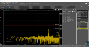
I did some SPICE modelling for that tube at exactly the operation point of my amplifier and I think mu follower is running exactly at the theoretical prediction. So from the image that I posted before with the spectrum it can be seen that H2 is -41dB down and 3rd is -56dB.
Now with the load line that mu follower creates and the modelled tube (see the screenshot) we get H2 at -49 db (0.35%) and H3 at -60dB (0.1%), so I will stick with my 270 ohm and not the suggested 330-470.
Now with the load line that mu follower creates and the modelled tube (see the screenshot) we get H2 at -49 db (0.35%) and H3 at -60dB (0.1%), so I will stick with my 270 ohm and not the suggested 330-470.
Attachments

Note to my above post #19- if you are using 2SK170 then you probably need to stay below 10mA continuous drain current. I am actually using LSK170D. Gee these things go out of stock it seems and then the prices get crazy. It's annoying.
Thanks for the link in post #20 istealth.
I found a few things with this circuit - one is that R6 really needs to be 10Meg or else you have to increase C1 which increases cost and will require more space.
Adding the gate stopper resistor as in Rev. 08 of the circuit is not a bad idea. I never used the SMD devices where the Ale experienced some oscillations, but added the resistor anyway.
It is probably a good idea to choose R4 carefully as well. I found a high value film resistor to be important here. In my tests, the LND150 network most stable at less than 1 mA. Right now I have it running only 0.5mA and it holds a very firm DC value. At 1mA it exhibited a little drift (but this could have been due to thermal issues as well).
Last edited:
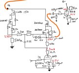
Indeed I took those things into account as well. So my actual schematics is below (B+ there is 410V). I use 2N7000 because it was tricky to source other transistors. DN2540 runs a bit hot, 1.5W dissipation but running for a couple of hours was not the problem, in the end I added a small heatsink. I think the difference in cost between 0.1 and 0.22 caps is not that big, I am not using anything fancy, Jantzen Superior, and Russian PIOs, those are all below 10euro per piece. I went with 4.7M/0.22uf combination, it is still a huge overkill (<1Hz for -3dB) because the -3dB frequency of my next stage to 300Bs due to RC coupling (0.22uf/220K) and is 6Hz, which perfectly matches the measurements. Going with higher values of caps will lead to blocking distortion. In the real tube-based mu-followers that cap is even smaller because it is actually bootstrapped as well, so typically it is 0.01uf ( http://www.valvewizard.co.uk/mufollower.html ). In the case of the hybrid mu follower, the limiting cut off is indeed due to RC (4.7M/0.22).
By the way, as a note, if one measures the Vref (as shown in the pdf of the original schematics), one will influence that measurement with the multimeter. I had this with 4 different ones. So when the circuit is running, it is good to measure the voltage set on a tube/anode. Touching the Vref point with the multimeter bring the voltage down from 270V to 160V in my case. So keep that in mind while debugging and configuring the voltages.
By the way, as a note, if one measures the Vref (as shown in the pdf of the original schematics), one will influence that measurement with the multimeter. I had this with 4 different ones. So when the circuit is running, it is good to measure the voltage set on a tube/anode. Touching the Vref point with the multimeter bring the voltage down from 270V to 160V in my case. So keep that in mind while debugging and configuring the voltages.
Attachments
I finally got IXTP08N100P and tried it in the schematics above, hoping that it will be just a plug in replacement but actually nothing works. When I use IXTP08N100P instead of DN2540 with all the components as before, without the tube, I can only regulate the voltage Vref or anode up to 200V, nothing more (for DN2540 I could easily go to 360V or so, where my goal was 250V). When I keep 180-190V on anode and connect the tube, the voltage just drops to tens of volts, very strange. The transistors are good (measured with a transistor tester before and after the experiment). Probably people who tried such swapping could help sharing what they did to their working schematics with DN2540... otherwise I will try to experiment a bit more this week.
I see my problem, those are enhancement and not depletion mode mosfets. So TME.eu also does not have D2 version, so still no good sources to buy in EU 🙂
The "D" or "P" is the type of case.
Are you sure, that wiring of FETs is OK?
I use this type of "gyrators" many times without any problem with various IXTP FETs.
BTW this operating point IMHO better, the THD almost the half of your choice.

Are you sure, that wiring of FETs is OK?
I use this type of "gyrators" many times without any problem with various IXTP FETs.
BTW this operating point IMHO better, the THD almost the half of your choice.
According to the manual IXTY08N100D2 is a "Depletion Mode MOSFET" and IXTY08N100P is a "N-Channel Enhancement Mode", so those are totally different modes, based on totally different physical principles and definitely not substitutable (https://www.electronicshub.org/mosfet/). It is not possible that IXTY08N100P works in that schematics, I can guarantee 🙂 It can "work" there (it will not burn, I tired), but it does not do the proper mu-follower operation. DN2540 is also depletion MOSFET, so it is replaceable 1:1 with IXTY08N100D2.
Indeed, I now have more or less the same operating point, mine is now 8mA and 250V on anode. I changed it recently, because the max power in class A driver for 6N7 is 2W, and I wanted as "much" current as possible to drive Miller capacitance of 300B, so I was pushing to 10-12mA, but then anode voltage should be 200V which also makes MOSFET too hot (dissipating 2W). In the end I went for something in between because I did not want to have current less than 7mA. I measured the THD in practice and in my case with 210Vpp I get 0.58% which is a nice coincidence with the simalution and not bad at all. I also tried to load those 6N7 with anode choke of 200H with the same conditions and the THD was the same. For such a large swing it is good, 300B in my case only needs 120Vpp.
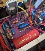
By the way the Rmu that I tried (of 390 and 470 Ohm) that produce noise, might be just of poor quality. I read that Rmu should be of high quality and indeed in my experiments they were of different types, 270 Ohm (which works great) is metal film, and 390 and 470 were carbon film. So the issue might be not with Gfs as discussed above but with crapy resistors. I will do some more tests soon. I was not thinking that it can be the issue (causing that extra noise background).
Indeed, I now have more or less the same operating point, mine is now 8mA and 250V on anode. I changed it recently, because the max power in class A driver for 6N7 is 2W, and I wanted as "much" current as possible to drive Miller capacitance of 300B, so I was pushing to 10-12mA, but then anode voltage should be 200V which also makes MOSFET too hot (dissipating 2W). In the end I went for something in between because I did not want to have current less than 7mA. I measured the THD in practice and in my case with 210Vpp I get 0.58% which is a nice coincidence with the simalution and not bad at all. I also tried to load those 6N7 with anode choke of 200H with the same conditions and the THD was the same. For such a large swing it is good, 300B in my case only needs 120Vpp.
By the way the Rmu that I tried (of 390 and 470 Ohm) that produce noise, might be just of poor quality. I read that Rmu should be of high quality and indeed in my experiments they were of different types, 270 Ohm (which works great) is metal film, and 390 and 470 were carbon film. So the issue might be not with Gfs as discussed above but with crapy resistors. I will do some more tests soon. I was not thinking that it can be the issue (causing that extra noise background).
Attachments
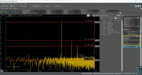
So indeed, the previously reported higher background noise for 360-470 Ohm resistors for Rmu was in my case due to type, metal film vs carbon film. Now I used metal film of 390 Ohm and the plots are nicely matching:
Attachments
Glad to get to the bottom of this. I would note that there are also very good quality carbon film resisters out there. Also, if you use a bigger heat sink you can bias for higher current (but this is obvious and I think your board doesn't have much space...
Last edited:
Aehm. So the general rule of thumb is to use Rmu = 1/gm, where gm is the transconductance of the FET at the given operating point. Looking at real-world examples that can't be right.
For example, looking at the 2SK170 datasheet, the diagram at the bottom left of page 2 indicates the transconductance around 25 mS for a drain current of 4 mA (the diagrams uses Yfs for gm). The corresponding Rmu would work out to 1/25mS = 40 Ohm. However, all examples and recommendations for Rmu with a 2SK170 are about 30x higher (around 1...1.5 kOhm).
The same can be said for Rmu values recommended with other FET types I find out there. What am I missing?
Hmm, I just ran into an issue with oscillations in a hybrid mu stage. Took me a while to get it, but once I realised there was too much feedback in the mu stage CCS I simply reduced the mu resistor value from 450Ω to 150Ω, and the oscillations were gone. The CCS FET is an AOT1N60.
What is your experience with this stuff?
Also, why do most mu stages use larger values than suggested from the Rmu = 1/gm rule?
What is your experience with this stuff?
Also, why do most mu stages use larger values than suggested from the Rmu = 1/gm rule?
I used Ale Moglia calculations and when measured are more or less the same https://www.bartola.co.uk/valves/2018/04/28/hybrid-mu-follower-output-impedance/
As far as I can tell, Ale does not explain why one would use 1/gm for the Rmu value. He simply uses Rmu=470...1.5k Ohm.
@merlin el mago Did you check for high-frequency oscillation with your hybrid mu-stage? Just hook up an oscilloscope to the output and take a look if there's anything (in the 0.1...10 MHz range or so).
@merlin el mago Did you check for high-frequency oscillation with your hybrid mu-stage? Just hook up an oscilloscope to the output and take a look if there's anything (in the 0.1...10 MHz range or so).
Gm is the tube's transconductance.So the general rule of thumb is to use Rmu = 1/gm, where gm is the transconductance of the FET at the given operating point.
View attachment 1324103
Rmu: 470R corresponds for 2.13mS tubes.
6SN7 has 2.6mS (at 250V, 9mA, fix bias).
801a has -about- 1.6mS at low voltages. I measured few bunch of 801a (210V, 18mA). The average is 1.69mS. The graphite anode 801 average Gm is 1.8mS.
Tendency of oscillation IMO depends of "lower" FET transconductance.
AOT1N60 has even 900mS (at 40V Vds). Without additional gate stopper (for example 1k carboncomp connected directly to gate pin) tends to oscillate.
AOT1N60 has even 900mS (at 40V Vds). Without additional gate stopper (for example 1k carboncomp connected directly to gate pin) tends to oscillate.
The "mu resistor" (Rmu) connected to the FET feeds any voltage variation from the Source pin back the Gate pin (via a DC blocking capacitor). The Rmu works like the sense resistor in a CCS made from a depletion mode FET (at least in the AC domain, see the Kimmel paper describing the hybrid mu stage). In other words, the FET/Rmu/blocking-cap form an AC-coupled CCS. I therefore don't understand how the Rmu would be related to the tube connected to the active load formed by the FET/Rmu. Previous posts in this thread and also the various notes by Ale Moglia seem to indicate the Rmu is chosen based on the parameters of the FET, not of the tube. But I may be wrong... if so, I'd enjoy some pointers to educate myself!Gm is the tube's transconductance.
Adding a grid stopper did not stop the oscillation in my case. What did help was to reduce the Rmu resistor, which reduced the feedback in the AC-coupled CCS.Tendency of oscillation IMO depends of "lower" FET transconductance.
AOT1N60 has even 900mS (at 40V Vds). Without additional gate stopper (for example 1k carboncomp connected directly to gate pin) tends to oscillate.
P.S.: the link to the attachment "1324103" in your previous post does not work.
Gm is the tube's transconductance.
View attachment 1324103
Rmu: 470R corresponds for 2.13mS tubes.
6SN7 has 2.6mS (at 250V, 9mA, fix bias).
801a has -about- 1.6mS at low voltages. I measured few bunch of 801a (210V, 18mA). The average is 1.69mS. The graphite anode 801 average Gm is 1.8mS.

- Home
- Amplifiers
- Tubes / Valves
- How calculate the Rmu resistor in an hybrid Mu follower