26+6+10 is lowest center for the horn. The stand can raise it over 10 more inches. 42 to 46 inches is perfect for ear height in a computer chair.From the height dimension you have chosen, perhaps you like you like to sit on the floor in the lotus position, or you like the sound source below you. I don't like either of those
If I need that I can slide my chair back a few feet and be in a perfect equilateral triangleAn equilateral triangle between the speakers and listening position is fairly typical.
Putting the subwoofers and front firing mid bass in the same cabinet is a self-imposed restriction that will reduce your positioning and proximity options,
What are my options already? I placing subs in or near the corner is already a desirable place.
Playing with the simulator I did not see a huge improvement with a subs arranged symmetrically in quadratic stereo. Also rear subs would require another amp/dsp. So far I can run everything with 2 amps in the fashion of a two way
being 32" and wide whats hard in the corner? They are faced angled so as big as they are, there is space between the pit of the corner. The right rear corner is 9inches away from the front wall and the left rear corner is about an inch away from the left wall, for example. Playing with vituix cad it seems Top, bottom and rear are the best positions. I'm leaning towards top and bottom with a 2nd order low pass near 120hz or so.Hmm, this + 1 m LP distance implies you'll be moving the speakers from near the chair to hard in the corners? This ideally puts all drivers on the front to moving the dual woofers to on the back or sides and 'gapped' to 'taste' in the corners, so best compromise in this case for me is one on each side.
Do you guys recommend a place to get premade passive crossovers from? Or maybe a certain brand...
I think I can wire all the woofers in parallel and then what, I need a passive crossover for each woofer in the circuit?
I think I can wire all the woofers in parallel and then what, I need a passive crossover for each woofer in the circuit?
being 32" and wide whats hard in the corner?
No side wall gaps and any space behind is packed with heavy damping such as one or more rolls of attic insulation, but once again no time to 'see' beyond your response(s) to me, so misunderstood your meaning of top/bottom, i.e. there would be a gap to floor, nor was aware there was a DIY program advanced enough to sim a speaker positioned anywhere along a corner; but yes, as it turns out my original "below' and recent 'rear' suggestions were spot on and now knowing it's spaced up, top/bottom too, though guessing rear (curious which) yields the highest 1/4 WL frequency.
Curious too as to where you're located.
That's unusual. I have yet to see a situation where distributing the subs around the room is not a substantial benefit. Maybe your sim is wrong, most are.My experiments with Rew room sim show no significant improvement by surrounding myself with quadratic stereo subwoofers.
Last edited by a moderator:

I am really doing myself an injustice by not trying to dampen the slot vs redesigning it 😩I think I can narrow it down to some visually interesting yet effective solutions
Cotton rope
Acoustic ceiling tile
Open cell foam
I think cotton rope is a good choice but importantly to me these options allow a uniform organized approach that would be visually pleasing if done right
This is cheap n thick

Cotton rope
Acoustic ceiling tile
Open cell foam
I think cotton rope is a good choice but importantly to me these options allow a uniform organized approach that would be visually pleasing if done right
This is cheap n thick
Last edited:
@gedlee @weltersys @GM
Thank you guys for your continued patience, there is one thing, I cannot simulate but I think your experience and knowledge could predict the outcome. please consider the effects of the use of damping material, as well.
There are 2 slot configurations I think could work.
One is a Tringle with a driver on each plane. This maintains equal force cancellation, and after damping material should have a decent FR

2nd Idea is a tetrahedron.
Basically a tetrahedron shaped waveguide with the woofers offset on the three planes. This would be better acoustically but not have as much force cancellation
Thank you guys for your continued patience, there is one thing, I cannot simulate but I think your experience and knowledge could predict the outcome. please consider the effects of the use of damping material, as well.
There are 2 slot configurations I think could work.
One is a Tringle with a driver on each plane. This maintains equal force cancellation, and after damping material should have a decent FR
2nd Idea is a tetrahedron.
Basically a tetrahedron shaped waveguide with the woofers offset on the three planes. This would be better acoustically but not have as much force cancellation
Attachments
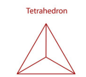
The tetrahedral orientation creates a conical horn, it could simulated in Hornresp.
The volume of the triangular cavity could be simulated in Hornresp same as a slot.
Damping material could reduce some of the cavity resonance.
Either triangular or tetrahedral orientation work OK for low frequency use.
Long term cone sag is a problem for either, and the effect of gravity compromises symmetry in use.
Simulation programs won't account for those, TS parameters are for vertical speaker alignment.
Most frontal area reduction schemes use two or four vertically oriented drivers in a "V" to avoid those problems.
The tetrahedron is not pure force cancellation, there is still up-down force - assuming three drivers. For this reason, I do prefer the triangle tube. This would make for a strong single source, but a single source in a room can be a disaster. I would prefer three small, but individually controlled subs spaced about the room - all closed box. Setup right and the bass in that system would be spectacular.
That looks like closed cell foam, and it is terrible for what you want. You need about 20-30 PPI open cell, or don't do it.I am really doing myself an injustice by not trying to dampen the slot vs redesigning it 😩I think I can narrow it down to some visually interesting yet effective solutions
Cotton rope
Acoustic ceiling tile
Open cell foam
I think cotton rope is a good choice but importantly to me these options allow a uniform organized approach that would be visually pleasing if done right
This is cheap n thick
How should I view multi sub versus corner loadeding. First I should say that I am not certain if corn loading has to literally mean dead in the corner, if that's the case then I am probably using the term somewhat loosely as I mean anywhere from in the corner to near the corner. When playing with the room simulator the further a woofer was moves into the corner the more improved the frequency of response was.That's unusual. I have yet to see a situation where distributing the subs around the room is not a substantial benefit. Maybe your sim is wrong, most are.
Dead in the corner is creates a great response. How does one improve upon that using more?
I am definitely not against multi subs surrounding but I do not wish to use anything that is not symmetrically placed around the listener. So when I play with the simulation I always keep the rear subs a mirror image of the front subs... I couldn't see wanting to do it differently, hopefully thats limiting on performance
Doing multi subs will require more electronics but as they say, you get what you pay for.
Last edited:
If the acoustic output ramps up as a result of cone break-up, won't that also cause the acoustic output of any distortion to ramp up in proportion to that increase in SPL?Everyone who has designed loudspeakers, knows that at a certain point distortion level will ramp up close to cone-break up.
Cone break-up happens at both low and high operating sound pressure levels, as it is a linear phenomenon. It's a pity that the term "break-up" implies some sort of breaking of the structure, when in fact it is simply undergoing a natural higher-order modal response. When a driver is operated within its nominal linear range, the break-up modes of the driver are simply the result of the mechanical stiffness and mass properties of the diaphragm.
I'm curious as to how the Klippel analyzers treat these two types of distortion: HD and IMD. How do they handle them differently?Okay explain to me this why people like Klippel take these different kinds of distortion [HD and IMD] very differently?
Having a reference threshold seems to simply be a reflection of the fact that "modern design practice" enables a certain level of performance to be achieved.They even provide a threshold reference in their graphs (I think it's around 3%) which indicates where either/or IMD or HD distortion is to high.
The problem is that "corner loading" in rooms is a fiction. A corner in an open field, i.e. no opposing walls, with have about 8 times more output (maybe even greater due to efficiencies) and that is across the band. But a corner in a room is a different animal altogether, because all dimensions have opposing walls and hence we now have constructive and destructive reflects leading to mades with lots and lots of gain as well as regions of almost no output. The later is obtainable, the former not so much. Hence, I wouldn't want to compare the two situations becau8se you can never achieve one of them. This complex situation is why DSP control becomes almost necessary, certainly necessary for a "premium" sound system.How should I view multi sub versus corner loadeding.
The double negative caught me at first. I have always proposed a r4andom placement as the most effective and I stand by that.Im definitely not against multi subs surrounding but I do not wish to use anything that is not symmetrically placed around the listener.
Don't rely on inaccurate sims, no one - to my knowledge - does the high distributed damping room sim right because iot massively complicates the algorithm.So when I play with the simulation I always keep the rear subs a mirror image of the front subs... I couldn't see wanting to do it differently, hopefully thats limiting on performance
Yea a couple more amps, I did it with a single 2 channel amp. But amps are cheap and so is the DSP. SUre its more complicated, but that's why it works.Doing multi subs will require more electronics but as they say, you get what you pay for.
Klippel has some kind of multi-tone distortion test.I'm curious as to how the Klippel analyzers treat these two types of distortion: HD and IMD. How do they handle them differently?
But I think they also have a test where they combine IMD as well as HD and check which of the two will be the most significant?
I don't know the exact details anymore on top of my head, you have to dive into the Klippel papers for that.
It's all quite well explained (well, most of it lol)
https://www.klippel.de/know-how/literature/papers.html
I totally agree with you that just one flat line isn't the greatest, very far from it even.Having a reference threshold seems to simply be a reflection of the fact that "modern design practice" enables a certain level of performance to be achieved.
But since there are no other standards, we have to use something.
A good read on this is;
https://hifi-selbstbau.de/index.php/hsb-grundlagen/verschiedenes/klirrfaktor-wie-viel-ist-zu-viel
(use google translate if you can't read German)
Or a couple Geddes papers obviously.
But unfortunately there is still no or very little general agreement on any of this.
Images say more than words;If the acoustic output ramps up as a result of cone break-up, won't that also cause the acoustic output of any distortion to ramp up in proportion to that increase in SPL?
I don't think we have to disagree that we don't want what's happening around 900Hz?
There are woofers which much worse issues.
In this case this woofer is big enough to not give us much trouble at lower frequencies.
With a smaller woofer that is more evident;
Some woofers ramp up far stronger than this one.
For 5 inch woofers this limit is often around 100Hz, for 4 inch woofers even (much) higher.
They could be still extremely good quality woofers, just not made for a lot of low-end.
Depending on you system design, that is sometimes also not needed.
For tweeters this is even more obvious;
Fact is that beforehand we have no clue to know where those limits are.
That is including very expensive high quality drivers.
In fact, in some (rare) cases these perform worse compared to other drivers.
So the idea of "high quality drivers" is most definitely not a guarantee for anything.
Maybe some of this is not important, but why would I spend more money into something if not needed?
Or why wouldn't I spend the same amount of money into something that performance objectively better?
The fact that we subjectively can't hear is, is not really relevant at that point.
Plus it potentially can gives us a bit more headroom BEFORE we ran into territory where we objectively CAN hear it.
I think we have the same amount of subs now, 6... So you ran 3 off of each channel of a stereo channelled amp? You then placed them to create the best FR you could? How Did you time align them if not done per woofer?Yea a couple more amps, I did it with a single 2 channel amp. But amps are cheap and so is the DSP. SUre its more complicated, but that's why it works.
That says it all.The fact that we subjectively can't hear it, is not really relevant at that point.
Last edited:
I have the same, three channels in front all 15", and three subs one 15 and two 12. The subs are all fed from the LFE channel on the receiver and I use amp in the receiver for one sub and add a stereo amp for the other two subs. The signals are all complicated DSP (LF only) based on room measurements - no two LF sources are the same. So there is a mix of stereo bass and mono. For some strange reason I have to cut the stereo woofers about 6 db at the rooms lowest mode. This mode is so easily excited. It is also in your sims. This mode is very hard to tame. ALl my room damping hardly has an effect.I think we have the same amount of subs now, 6... So you ran 3 off of each channel of a stereo channelled amp? You then placed them to create the best FR you could? How Did you time align them if not done per woofer?
I am sure a smart guy like you understand the bigger picture.That says it all.
Please don't quote bits out of context anymore, thank you.
- Home
- Loudspeakers
- Multi-Way
- Is it possible to cover the whole spectrum, high SPL, low distortion with a 2-way?