Hi, there's a mistake in schematic. Q7 and Q8 should be swapped, and then their collector -emitter too. Must be like in other schematics.
I do not agree.Hi, there's a mistake in schematic. Q7 and Q8 should be swapped, and then their collector -emitter too. Must be like in other schematics.
With corrected schematic it's ok. When positive input supplied to Q1 base ,Q1 will close ,collector current decrease, voltage drop on R6 decrease ,Q4 close ,Q5 current source pulls up all output positive ,output becomes positive .Errors in schematic were corrected .Now it should work ,except missing power rails decoupling .These are critical . I would suggest adding few capacitors ,to power ground ,close to output transistors .One smaller ,something like 0,1-1uf ,and one bigger ,like 470-1000uf ,for each polarity supply .Also , signal ground and power ground should not be mixed together directly , use a resistor of 10ohms to prevent ground float if not connected in power supply star ground.Normally power ground and signal grounds are joined together only at this place ,star ground .
But again ,simulate this first , to ensure there are no oscillation with resistor and capacitor values used .Sometimes a capacitor in parallel to R9 is needed ,estimate space for it on pcb .
But again ,simulate this first , to ensure there are no oscillation with resistor and capacitor values used .Sometimes a capacitor in parallel to R9 is needed ,estimate space for it on pcb .
Was schematic in post 1 edited ?
BTW for a circuit like this it should be possible to find ready made boards.
BTW for a circuit like this it should be possible to find ready made boards.
Built & test completely sounds very good also punchy bass.
Needs some improvements amplifier is quite playing loud music will update the schematic for further improvements.
Special thanks to Mooly sir & other diy members.
Also need pcb for this amplifier.

Needs some improvements amplifier is quite playing loud music will update the schematic for further improvements.
Special thanks to Mooly sir & other diy members.
Also need pcb for this amplifier.
Q6 needs thermal connection to heat sinks to sense temperature of output transistors—- part of PCB design.

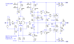
Hi. One comment. Try also in simulator following : replace R21 and R22 with single resistor same summary value, just between emutters of Q7 and Q8 , and 1uF in parallel. In case of oscillation or just high frequency prevent shoot-through current when both output transistors are conducting, increaes turn -off time. With arrangements like in schematic, turn off is slow, and turn on faster, and with high amplitude of high frequency when one transistor is turned on , other may not be turned off yet.
- Home
- Amplifiers
- Solid State
- Z100D Amplifier