I am fascinated with this driver, enough to order a second unit. It is this massive chunk of metal and magnets that just about fills out its 6.5" form. It also costs the same as 50g of tobacco! Its 171mm overall width is very useful to me, so the main fascination is its solid build and tiny 2.7L Vas.
With now two false starts with using this driver, let's just mess with it for giggles and see if an LF use can be made. One pair is definitely going into may car's front doors in custom pods with ports tuned to 60hz in an active two-way with a pair of FR speakers on the dash
While spending countless hours moving the cursor around in the box drawing in WinISD with reflex/PR systems, I have noticed its sensitivity to plunge from low 80dBs above its 70hz Fs to a steady 77dB 1w/1m below it till about 27hz where it goes weird but nothing else crazy in the sims apart from lower output. Nothing to indicate that the driver is in distress
77db is audible, let's treat it as a 77dB per 1w/1m sub. Can anything useful be done with an efficiency of 77dB with a 300wrms amp and a 600wrms amp?
Below Fb response drops at ~24dB per octave.One pair is definitely going into may car's front doors in custom pods with ports tuned to 60hz in an active two-way with a pair of FR speakers on the dash
77dB at ~60Hz, around 53dB at 30Hz..let's treat it as a 77dB per 1w/1m sub.
It would be useful to measure a cabinet of known sensitivity outdoors, then compare it in your car to find what it's cabin gain does to it's response.Can anything useful be done with an efficiency of 77dB with a 300wrms amp and a 600wrms amp?
There is a JLAudio 12” sub in the boot. What is missing though is output between 100hz to around 400hz. I have tried the stoutest of the woofers from 6.5” splits but killed them all. This is the bottleneck that doesn’t let volume to be raised high with Sly and Robbie dub basslines
Thats one use. I am still without any real options on creating the size and range of sound that can fit on the near field desk top use. The Dayton Epiques were the first to be ruled out with easily exceeding Xmax and the Tang Band is only available from PE with massive shipping costs
With two units to play with, I am also curious to explore a dual opposed setup if they can work with a bass reflex system. I don’t know how to set this up in WinISD
Some new measurements today from the z623 subwoofer only. At the 1.8m listening position. C weighted and set to fast. Sweep is from 30hz to 100hz. There is around 6dB droop between 30hz and 40hz and then very steady with peak variance under 2dB up till 100hz
These are the levels to at least meet or even better exceed in a stereo desktop subwoofer pair as bottoms for the FR drivers in a slim mini tower type cab. Constraint is 180mm width, 300mm depth. Height wise, around 300mm to 400mm tall, with the lower height preferred
I am open to suggestions for other drivers that can work in a cab of around 14L max internal driver volume and meet these levels and also those that can exceed the performance of the ZR6.4D when modelled in the same cab constraints
Lively average 85dB
Daytime average 77dB
Evening average 64dB
Late night average 58dB
Anyway lets place the ZR6.4D into a WinISD 14L BR tuned to 42Hz and see what happens at 1w, 10w and 300w
And then repeat that with some parametric eq with a bit wider Q set to 1.5 and 10db boost at 1w and 10w and see if the z623 numbers can be met at all
I came across a comment somewhere about calculating required PR moving weight but can’t find it again. Something about doing a WinISD sim with port dia set the same as the desired PR Sd. Then calculating the weight of the air in the port
Does anyone know right way?
Does anyone know right way?
The calculation you are looking for plus more..
Thanks to Tom Danley and Deon Bearden of the DIY Loudspeakers Mailing List for providing these guidelines for designing Passive Radiators systems:
Passive radiator systems are very similar in operation to ported systems. However, instead of a port, the passive radiator system uses a passive radiator (also known as a "drone cone") to extend the system's low frequency response.
The response of a passive radiator system is similar to that of a ported system using the same driver. However, the cutoff (-3dB) frequency is slightly higher, and the cutoff slope is deeper, mostly due to the presence of a "notch" in the frequency response corresponding to the passive radiator's resonance frequency. However, this notch is normally located far outside of the passband of the system, and therefore usually of little audible significance. The larger the passive radiator, the lower the passive radiator's resonance frequency (for the same target Fb), and the further the notch is out of the passband.
To design a passive radiator alignment, start with a simple ported alignment using that driver that provides the desired box size and frequency response. Then, use the diameter of your chosen passive radiator as the "port diameter", and use this to calculate the required port length. Work out the volume occupied by this port and then use this to calculate the mass of air occupied by this port. The result is the required mass of the passive radiator. If it is too small, use a larger passive radiator and repeat the calculations.
Example:
Driver: Vas: 2 cu.ft.
Qts: 0.30
Fs: 30 Hz
Diameter: 8 in.
Ported Alignment (QB3): Vb = 0.70 cu.ft.
Fb = 39.4 Hz
Now, we need to select an appropriately-sized passive radiator. ALWAYS use a passive radiator that is larger in diameter than the active driver, as the displacement of the passive radiator usually has to be 1.5 to 2 times that of the driver. If it's not possible to use one large passive radiator, then you can use two or more smaller ones, and tune them by working out the effective diameter from the combined surface area of the radiators.
Note that the effective diameter of the radiator is approximately equivalent to the diameter of the passive radiator's face plus 1/3 of the surround. If unsure, use the quoted Sd for that radiator, then use the following equation to determine the effective radius:
R = (Sd/PI)^0.5
In this case, we choose to use a passive radiator that has an effective radius of 5 inches (roughly corresponding to a "12-inch" passive radiator).
"Port" Radius = 5 in.
Required Port Length = 186.1 in.
"Port" Volume = (PI*R^2)*h
= (3.14 *5^2)*186.1
= 14609 cu.in.
= 8.45 cu.ft.
= 0.2393 m^3
Mass = "Port" Volume * Density of Air
= 0.2393 * 1.21
= 0.289553 kg
= 290 g
The passive radiator therefore has to have a weight of 290g. To achieve this, start with a passive radiator with lower mass, then add weight to make up the difference. To measure the resonance frequency of the passive radiator, install it in a free-air baffle (e.g. the box it's going in, without the driver in place), then hold a driver, driven by a sine wave generator, as close as possible to the passive radiator, then vary the frequency. At the passive radiator's resonance frequency, you should see the greatest peak to peak excursion of the passive radiator.
Like their ported cousins, passive radiator systems are much more sensitive to misaligned parameters than sealed enclosure systems, which makes their construction more difficult for the beginning DIYer. I advise that you don't attempt to build these systems, unless you're certain that the T/S parameters for the driver that you want to use are correct.
Almost any driver can be used in a passive enclosure system, however, only drivers which have a Qts value between 0.2 to 0.5 will generally give satisfactory results. If the driver has a Qts above 0.4, try using it in a sealed enclosure or single reflex bandpass system instead.
Indeed, very appreciative of Tom Danley and Deon Bearden for sharing and educating. Equally appreciative of your work, interests and how you support us noobsThanks to Tom Danley and Deon Bearden of the DIY Loudspeakers Mailing List for providing these guidelines for designing Passive Radiators systems:
Armed with that info, I will be able to make some passive radiators to test. Dual 8s are exceeding Xmax in the previous sims. I need something like the SLAPS unit
One difficulty that I keep having is port proportions. Decided to go with a small 47mm port for initial testing, as WinISD shows port air speed minimal at 10w. Let's see how bad that chuffs. Even at the subs peak levels. I have some ideas to try out on cleaning that up so more fun
For eventual PRUs, lets aim for dual 8". So one sim will be with a pair of 142mm dia ports. Will try to get my head around the process that Art shared in post #6 and figure out moving mass
A DIY PRU can be the subject of a thread if there is interest in helping me develop a make at home system. I can develop the workflow easy enough but struggle with the acoustic engineering. Already have the process for creating custom surrounds and diaphragms that still needs proof testing, Another hurdle for me is engineering a compliant mech spider that can be laser cut
So, our 20L box needs a port that's >15 feet long & occupies 239L? 🤔Example:
Ported Alignment (QB3): Vb = 0.70 cu.ft.
In this case, we choose to use a passive radiator that has an effective radius of 5 inches (roughly corresponding to a "12-inch" passive radiator).
"Port" Radius = 5 in.
Required Port Length = 186.1 in.
"Port" Volume = (PI*R^2)*h
= 0.2393 m^3
Also, this method ignores the PR's suspension. How does that affect the tune at varying drive levels?
The 2nd ZR6.4D and the ZR12.4D arrived today, but the 12"er is its own weird lil project that must be completed and well tested by August. My highest priority audio project now, I took a date for live use in August. My current unit performed there last night, providing low bass reinforcement in a cinema sized hall. I try to upload a small clip of it in full swing later
Ordered materials to try my hand at a pair of DIY passive radiators with diaphragm dia at roll surround inner being 142mm, but that's its own project too
Ready to start some serious sims for the ZR6.4D based desktop subwoofer/bottoms pair. Target is meeting or exceeding 85dB at 1.8m over 40-300hz band flat as well as with a loudness compensation curve. 40L is the max driver volume available. If the sims look promising, then the test boxes will be built from 16mm MDF and with 47mm port diameters. If the design plays ok, then will do a proper build using passive radiators from the DIY project. No urgency on this one but with so much work already gone in, I'll give it a few more days of sims and then start work on the 12". Will use offcuts from that to make the test box for the 6.5" at the same time
The previous post has a major typo. The max volume allowed for the driver is 14L
Sims for flattest well under 40Hz
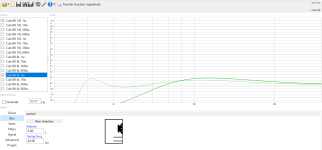
Frequency response
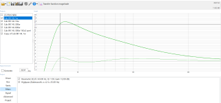
Adjusted the display window to show expanded view of the curve within the targets of +/- 3dB for response and use band from 30-300Hz. Looks so wavy

SPL
The lowest trace is 1w and the highest is 600w. The pane on the left shows running and active projects

Cone excursion

Group delay

Learning to use the tool. Looks like group delay is just getting into the lower end of the unavoidable
https://audiojudgement.com/group-delay-explanation-measurement-audio/

Transfer function phase
Have tried to read up on how to interpret this graph, I can read how the phase changes over the band but I dont know how to tell if this is a good or bad result

Impedance
The amp modules have an integrated PSU and setup to do equal power in 4R/8R

Port air speed
At higher powers, it resembles a cat5 cyclone blast!
I need assistance if figuring out if I am looking at exceeding 10w at the listening position. Note, there will be two cabs in stereo and the sims are for a single cab. Also, assistance with how much output I can expect before audible artefacts become a problem. Note, eventually the port will be replaced by a dual opposed passive radiator system

Frequency response with filters on
The pane on the left shows running and active projects. The lower trace is a copy of the 1w with filters off to show original trace

SPL with filters on
The pane on the left shows running and active projects. The lower trace is a copy of the 1w with filters off to show original trace

Group delay with filters on
The pane on the left shows running and active projects. The lower trace is a copy of the 1w with filters off to show original trace

Impedance with filters on
The pane on the left shows running and active projects. The lower trace is a copy of the 1w with filters off to show original trace

Transfer function phase with filters on
The pane on the left shows running and active projects. The lower trace is a copy of the 1w with filters off to show original trace

Cone excursion with filters on
The pane on the left shows running and active projects. The lower trace is a copy of the 1w with filters off to show original trace

Port air speed with filters on
The pane on the left shows running and active projects. The lower trace is a copy of the 1w with filters off to show original trace
This is now a storm on Jupiter class gust in the upper powers. I need assistance to determine in port noises are likely to be an issue when matching the indoors 86dB levels over the subwoofers use band

Now this is the port air speed trace with dual 142mm dia ports. Length is 3.73m. I will try to use the material that Art provided to work out the moving mass needed for a pair of PRs. I found an article on SBA website re PRs that may help workout the compliance for the suspension
Would really appreciate some feedback from the forum if the sims look worth further pursuing as stereo desktop subs for near field? The tops would be a pair of 3" FR drivers in their own volumes. I'll prolly end up using a pair taken out from the z623 or Tang Bands if I can manage the shipping on them
Sims for flattest well under 40Hz
Frequency response
Adjusted the display window to show expanded view of the curve within the targets of +/- 3dB for response and use band from 30-300Hz. Looks so wavy
SPL
The lowest trace is 1w and the highest is 600w. The pane on the left shows running and active projects
Cone excursion
Group delay
Learning to use the tool. Looks like group delay is just getting into the lower end of the unavoidable
https://audiojudgement.com/group-delay-explanation-measurement-audio/
Transfer function phase
Have tried to read up on how to interpret this graph, I can read how the phase changes over the band but I dont know how to tell if this is a good or bad result
Impedance
The amp modules have an integrated PSU and setup to do equal power in 4R/8R
Port air speed
At higher powers, it resembles a cat5 cyclone blast!
I need assistance if figuring out if I am looking at exceeding 10w at the listening position. Note, there will be two cabs in stereo and the sims are for a single cab. Also, assistance with how much output I can expect before audible artefacts become a problem. Note, eventually the port will be replaced by a dual opposed passive radiator system
Frequency response with filters on
The pane on the left shows running and active projects. The lower trace is a copy of the 1w with filters off to show original trace
SPL with filters on
The pane on the left shows running and active projects. The lower trace is a copy of the 1w with filters off to show original trace
Group delay with filters on
The pane on the left shows running and active projects. The lower trace is a copy of the 1w with filters off to show original trace
Impedance with filters on
The pane on the left shows running and active projects. The lower trace is a copy of the 1w with filters off to show original trace
Transfer function phase with filters on
The pane on the left shows running and active projects. The lower trace is a copy of the 1w with filters off to show original trace
Cone excursion with filters on
The pane on the left shows running and active projects. The lower trace is a copy of the 1w with filters off to show original trace
Port air speed with filters on
The pane on the left shows running and active projects. The lower trace is a copy of the 1w with filters off to show original trace
This is now a storm on Jupiter class gust in the upper powers. I need assistance to determine in port noises are likely to be an issue when matching the indoors 86dB levels over the subwoofers use band
Now this is the port air speed trace with dual 142mm dia ports. Length is 3.73m. I will try to use the material that Art provided to work out the moving mass needed for a pair of PRs. I found an article on SBA website re PRs that may help workout the compliance for the suspension
Would really appreciate some feedback from the forum if the sims look worth further pursuing as stereo desktop subs for near field? The tops would be a pair of 3" FR drivers in their own volumes. I'll prolly end up using a pair taken out from the z623 or Tang Bands if I can manage the shipping on them
Attachments
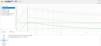
Continuing on from the previous post. That was the driver in the largest allowed volume for my purpose. Largest allowed doesn't mean it an optimum in all areas. A presence of this sized pair still intrudes into the small room, but is the most that I would want to live with if that's what it took to match the z623
Same sims of the same tuning and filters in a 6L driver volume. Running projects can be seen in the left pane in the graph pics. Active are the 14L and 6L sims. The lower traces in each pair are the 6L volumes. The inactive 10L and 8L sims stepped in neatly but makes the screen too busy if all are activated
14L vs 6L sims
Frequency response with filters off
At 6L, a -3dB prediction for 53hz, compares well if seen in context as bass response on a bookshelf when compared to the 60-90hz F3 for desktop 2-ways that I normally see out of comparably sized boxes

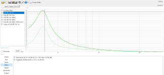
Frequency response with filters on
A -3dB @ 33Hz out of a 6L driver volume. Who can beat this and the group delay and SPL numbers coming up?

SPL with filters on
The lower trace in each pair is the 6L

Group delay

Excursion with filters on

This is how I interpret these results, might not be correct due to inexperience, To me, the 6L cab slightly falls short of the SPL numbers when compared to the 14L cab. Otherwise, it betters the group delay numbers. It also shows much more lower end performance than what can usually be found in a tiny around 6L
Both design sizes appear very worthy of exploring further, with a pair of cabs in each size. I'll move on to the 12" project now and assemble these test boxes from the offcuts of that project
Same sims of the same tuning and filters in a 6L driver volume. Running projects can be seen in the left pane in the graph pics. Active are the 14L and 6L sims. The lower traces in each pair are the 6L volumes. The inactive 10L and 8L sims stepped in neatly but makes the screen too busy if all are activated
14L vs 6L sims
Frequency response with filters off
At 6L, a -3dB prediction for 53hz, compares well if seen in context as bass response on a bookshelf when compared to the 60-90hz F3 for desktop 2-ways that I normally see out of comparably sized boxes
Frequency response with filters on
A -3dB @ 33Hz out of a 6L driver volume. Who can beat this and the group delay and SPL numbers coming up?
SPL with filters on
The lower trace in each pair is the 6L
Group delay
Excursion with filters on
This is how I interpret these results, might not be correct due to inexperience, To me, the 6L cab slightly falls short of the SPL numbers when compared to the 14L cab. Otherwise, it betters the group delay numbers. It also shows much more lower end performance than what can usually be found in a tiny around 6L
Both design sizes appear very worthy of exploring further, with a pair of cabs in each size. I'll move on to the 12" project now and assemble these test boxes from the offcuts of that project
Attachments
A port would not need to be 10" diameter for an 8" driver.So, our 20L box needs a port that's >15 feet long & occupies 239L? 🤔
The slug of air in a port does not have a specific excursion limit, a PR does.
If the port was 10" diameter, for an Fb of 39.4Hz and a .7 cubic foot box it would be ~15 foot long.
That said, it would then be a tuned pipe rather than bass reflex..
From what I can gather from Josh Ricci's measurements, the Fb using PRs appears to lower in frequency at higher drive levels.Also, this method ignores the PR's suspension. How does that affect the tune at varying drive levels?
https://data-bass.com/#/systems/5c2e78ff80141f000411fc28?_k=xfp69d
The above tuning dropped about 1Hz, not much from 25Hz.
Lower tunings require more mass to be added to the PR, and seems to increase the relative drop in Fb, from ~18Hz to ~15.7Hz:
Last edited:
DS18 have run out of stock of the ZR6.4D, folks are taking notice what this driver can do
The 6L sims appear to set a new standard for simulations of powerful low bass out of a cab in this class by significantly bettering a proven and tested THX rated sub. I was already fascinated by the massive build of this small 6.5" driver, and now have a new respect and hope for decent real life results for authoritative musical bass
I think this pair in hand here are going to get even more special attention on my part
- Home
- Loudspeakers
- Subwoofers
- Exploring and developing with the ZR6.4D