Is it the previous blue board FSP or the last black board with switches UFSP? What kind of noise, hiss or hum?
There are no reports of this RIAA becoming noisy after time for some specific reason so to can point you directly.
First areas to check for noise should be the input stage JFETs and the regulator. Semiconductors in general and solder joints.
If it is the UFSP, work the little switches (while powered off) to self-clean in case dirt or oxides went into their contacts.
Also clean solder flux remains on the board if any. They can become conductive after some time and create gate leakage paths.
Scope B+ rail vs the non noisy channel's B+ rail on AC coupling and mV vertical scale, see if the noise is coming from the shunt regulator supply.
Thanks,
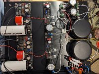
It is hiss noise, the board is Black, Was not use dip, soldered a wire via instead of.
Try to resolder all joint,
The board is/was clean,
The power supply noise same both chanel,
Chane the 2-2pc PRP (red) resitor to Takaman, but same,
The main issue to find that small mV or lover noise is not easy task...

Indeed its not an easy task. Difficult to be due to a passive part gone bad. And its not hum but hiss so its not due to a ground loop. What sensitivity level you set with a link wire?
Since both channels power supplies noise is at same level concentrate on signal stages:
-Follow the signal path with the scope's probe and compare gone hissy channel and quiet channel. To try see on which stage's output their noise differentiates.
-Input gain stage is the 2SK369 duet in parallel & BC327 outputting on R4, 2nd gain stage is the single 2SK170, output buffer stage is the 2SK170 duet in series.
-Replace semiconductors in the noisy stage. One by one or altogether.
Thanks good idea,
Yes, I was try to shorted the input too,
Will swap the power supply later to check it.
It nearly not possible to measured with my equipment, (Siglent 824XHD) either the FFT either the normal scope pictures same but the equipment noise floor close or equal it.
What is really great ther is practically 0 hum,
That's a 12bit scope. You can't do much better for scope SNR & FFT. For more SNR you go to 24bit audio card and software like REW or ARTA etc.
Is there any difference in the signal output of the channels too?
Make voltage divider 1k series & 10 Ohm to ground. Feed 1kHz 100mV sine from the function generator to the 1k side, creates 1mV output to the phono from the 10 Ohm side. Compare gain of channels and noise of the output sine waves.
Is there any difference in the signal output of the channels too?
Make voltage divider 1k series & 10 Ohm to ground. Feed 1kHz 100mV sine from the function generator to the 1k side, creates 1mV output to the phono from the 10 Ohm side. Compare gain of channels and noise of the output sine waves.
Hi Tamra,
Readjust Ubib output (rail voltage) until hitting 4V T.P goal. 34V is just a start point. Go bit lower progressively in your case.
Readjust Ubib output (rail voltage) until hitting 4V T.P goal. 34V is just a start point. Go bit lower progressively in your case.
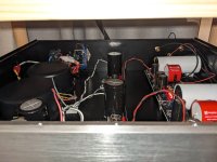
And it keeps gain setting relatively low because MM. Which is good for low electrical noise in a single chassis build that includes transformers and AC mains wiring in the vicinity of signal connections. Although Tamra's specific build looks well spread and the transformers have covers.
Hi Patrik,
You can alternatively use a computer audio output as 1kHz sine generator. The voltage divider will also attenuate the computer output's noise and the result will be clean enough.
You can alternatively use a computer audio output as 1kHz sine generator. The voltage divider will also attenuate the computer output's noise and the result will be clean enough.
MM setting always wants less rail voltage than MC setting for T.P. adjust due to single 2SK369 selected and less bias current in it. That is why you had to go lower from 34V to meet 4V T.P. Very normal. Each sensitivity setting with the DIP switches also wants a little different optimum rail level point to readjust.It's VM95ML.
I want to try MC cartridge later.
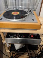
The cart you use is very decent and its probably a good much for your vintage Yamaha turntable. Is it a new cart or you had listened to it before on the same table with another phono?
Is it mean if I adjust R20 value?Each sensitivity setting with the DIP switches also wants a little different optimum rail level point to readjust.
I am very new to vinyl set up.
I grew up with cassette tape and CD.
I started with cheap Pioneer XL1550 and VM95E,Elekit PS3250.
Then my friend gave me good condition Yamaha yp700c with 10000yen.
I preferred Yamaha probably belt drive might be quieter.
Then bought new VM95ML for my interest.
It sounds a little accurate.Both sounds good to me. I have no experience with MC cartridge but I would like to spend for vinyl first.
PS3250 is ok but I was loosing interest to vinyl.
I was listening UFSP for while,I feel like this is what I expected to audio set up.
I want to buy more vinyls.
It means you usually need readjust Ubib output with its VR1 trimmer a little different to easily find 4V T.P for each different sensitivity you set with the switches (MM HMC MC LMC).
Have a good start with vinyl. You already put together a nice combination.
I see in your turntable's user manual that its original CG-7000 cartridge was 17mm tall and your VM95ML is 17.2mm so vertical tracking angle (VTA) should roughly be in the right area. That must not be the cause of little accurate sound then. It must be due to the microlinear needle profile. Tonally different but still informative is the Shibata. Nude elliptical lasts less hours, its also cheap, and it sounds more like older classic carts sacrificing some information. That's the orange VM95EN replacement needle.
- Home
- Source & Line
- Analogue Source
- Simplistic NJFET RIAA