See this and following posts as to why 7kHz + 13kHz is a very good and practical two-tone signal for IMD testing, and probably better than single sine THD (and especially those above 20kHz) and better than 19+20kHz IMD or (199+200kHz for that matter).However, since music signals are not suitable for measurement purposes, I think it makes sense to extend the measurement frequency for the sinus signal much more further outside the audio range - I would say between 100KHz and 300KHz. And for IM measurements a two tone sine wave 199KHz+200KHz.
For peace of mind we may want to generously extend that to 3x, that is, 21+39Khz and test within a 60kHz bandwidth. Beyond that point any gear should have effective low-pass filters anyway.

Could someone please point me to a good high fidelity preamp schematic using OPA828 / OPA2828? Balanced out and EMI filter would be a great option with a 6-20db changeable gain. 🙂
good advice, thank you therefore.See this and following posts as to why 7kHz + 13kHz is a very good and practical two-tone signal for IMD testing, and probably better than single sine THD (and especially those above 20kHz) and better than 19+20kHz IMD or (199+200kHz for that matter).
For peace of mind we may want to generously extend that to 3x, that is, 21+39Khz and test within a 60kHz bandwidth. Beyond that point any gear should have effective low-pass filters anyway.
Unfortunately, at the time when I was thinking about good amplifier circuits and trying out a few topologies with "Circuitmaker" around 2005 to 2011, I didn't know this yet. I came up on those days with the idea of working at the simulation level with measurement frequencies far outside the audible range and thus found some good topologies and learned that very simple circuits are often superior to the very complicated versions with extremely low THD values concerning sonic character.
See this and following posts as to why 7kHz + 13kHz is a very good and practical two-tone signal for IMD testing, and probably better than single sine THD (and especially those above 20kHz) and better than 19+20kHz IMD or (199+200kHz for that matter).
Very interesting. Thank you.
I’ve compared power amplifier measurements and don’t see, in this particular case, what better insight would 7/13 kHz test provide. I believe that, as is usual, it is better to make even more measurements and then try to draw conclusions. This can be considered as measurement of OPA828 as a first stage in power amplifier. Half of measured distortion is DAC contribution. 🙂
Final measurement is 31 tone signal which produces 16 Vpp at amplifier output.
Attachments
I am looking to upgrade an active crossover which has TL071 to OPA828 op-amps.
Aside from the mechanics does anyone think that will be a problem?
Aside from the mechanics does anyone think that will be a problem?
Despite its high GB product of 45 MHz, the opa828 has a straightforward one-pole characteristic, so it is forgiving of board traces and other problems, and operates stably even when used with 100% feedback. It will probably operate stably as long as the basic precautions are followed, such as decoupling of the power supply line close to the IC.
Note that the current consumption is four times that of the TL071.
However, if the original circuit is for TL071, since it may be an old design and the value of the peripheral circuits (especially the impedance of the filter CR at the crossover) may not be suitable for OPA828, it may not be worse than TL071, but may not bring out the full performance of OPA828,
Do not expect too much when rolling only OP-AMPs.
It would be very interesting for me to know how the IM residual distortion curvature looks in this two-tone (7+13Khz) measurement, if one do the same measurement procedure as the magazine "STEREOPHILE" do with the normal THD measurement for getting Fig. 6 underSee this and following posts as to why 7kHz + 13kHz is a very good and practical two-tone signal for IMD testing, and probably better than single sine THD (and especially those above 20kHz) and better than 19+20kHz IMD or (199+200kHz for that matter).
For peace of mind we may want to generously extend that to 3x, that is, 21+39Khz and test within a 60kHz bandwidth. Beyond that point any gear should have effective low-pass filters anyway.
https://www.stereophile.com/content/bryston-3b-st-power-amplifier-measurements
and fig. 8 under
https://www.stereophile.com/content/technics-su-g700m2-integrated-amplifier-measurements
What would you expect to see?
Anyway, to look at the residual, you'd need to completely notch out the test signal from the DUT output, and IMO that would be complicated. A distortion analyzer would normally use an auto-tuning notch filter to suppress the (only) fundamental. With a two- or multi-tone test signal, you'd need two or more auto-tuning notch filters, and I have not seen that done.
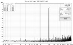
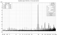
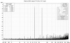
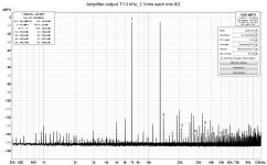
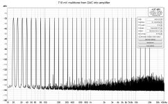
In contrast, it is easy to reduce the test signal in the DUT output by 50-60dB, enough to keep the ADC from adding its own IM products, so that the spectrum shows you IM products from your DUT and not from your measurement rig. However, the resulting signal is still dominated by the test signal, and that's what you'd see on the 'scope:

Anyway, to look at the residual, you'd need to completely notch out the test signal from the DUT output, and IMO that would be complicated. A distortion analyzer would normally use an auto-tuning notch filter to suppress the (only) fundamental. With a two- or multi-tone test signal, you'd need two or more auto-tuning notch filters, and I have not seen that done.
In contrast, it is easy to reduce the test signal in the DUT output by 50-60dB, enough to keep the ADC from adding its own IM products, so that the spectrum shows you IM products from your DUT and not from your measurement rig. However, the resulting signal is still dominated by the test signal, and that's what you'd see on the 'scope:
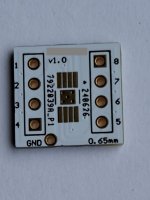
Any chance you could make the (adapter for HVSSOP to DIP 8 including thermal pad for the 2828) available, or the PCB design file?I made a small adapter for HVSSOP to DIP 8 including thermal pad for the 2828. It was a challenge to get it soldered. The sound of this OPAMP is indeed bliss, and extremely neutral with a very wide soundstage. I can understand why people, like the 627, might feel it sounds 'thin'. It's very, very transparant with lots of micro detail, yet it doesn't hurt your ears. Not a hint of sybilance when decoupled properly.
I did it using this adapter for soic8 with thermal pad. You need to bend the amplifier leads very carefully, it can easily be damaged. The soldering was done under a microscope. Without certain skills it is better not to repeatAny chance you could make the (adapter
Attachments
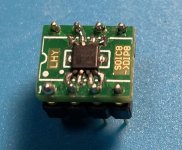
But here we need a thermal pad for this op amp, not only adapter. By the way they are really worm. I'll measure the temperature with a pyrometer if I can find one.SOIC8 one side and TSSOP8 the other
I designed my own PCB for the OPA8282 TSSOP in the end - with thermal pad on both sides and covering a lot of the PCB's area (under the ident).I did it using this adapter for soic8 with thermal pad. You need to bend the amplifier leads very carefully, it can easily be damaged. The soldering was done under a microscope. Without certain skills it is better not to repeat
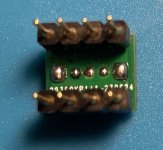
There is a place for 2 x decoupling caps from the +/-, and a ground pin as well.
If anyone wants to buy some bare PCB's for the dual Op Amp OPA2828 let me know as I have spares.
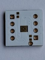
For myself, I sent the PCB and chips out to a specialist company who has automatic laser/ hot air soldering machines to do the chip mount.
I did try to solder myself on another board but was only 30% successful. The problem I found was bridging, and then going to clear the bridge either broke a pin, or ripped across breaking a track. So on my PCB I routed the tracks outwards and well away from the chips pins, in case someone is trying to hand solder them.
On the one I did successfully solder, the chip got very hot on the stock TSSOP PCB with no thermal pad, just like Anatolii said - so I don't recommend that route.
Attachments
Last edited:

@Mark Johnson
That really depends on how experienced you are at soldering. It comes with years of experience to start with and some thin solder. Having the equipment you mention is a big expense for a small amount of fine pitch work.
Even using paste and stencil you still need to place the part without disturbing the paste, easier said than done.
I guess I am unique or lucky that I am myopic and have a steady hand at 65, but am able to hand solder 0.5,0.65mm pitch without need of magnification. A QFN/DFN is the most challenging part for me to hand solder, it’s doable but the pads should be extended enough to have the solder tip touch the pad without disturbing the parts, it’s tricky and not for the inexperienced.
On that adapter designed for a thermal pad, if you put a large via in the middle you are able to get solder to flow through the via to get at the thermal pad under the device. But once done, if you want to remove the part then you will need liquid solder flux and hot air to remove the part, so it’s technique and experience that counts of course.
Looking at that example above, sorry to be critical but that’s aweful
Last edited:
TSSOP, VSSOP can be soldered with ordinary hand soldering, but with the help of a vacuum pump and a lot of liquid flux.It is normal that experience with a soldering iron is required. Pictured is DIR9001, TSSOP28.
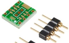
Mouser offers this adapter for op amps from TI that makes it a little easier.
Mouser offers this adapter for op amps from TI that makes it a little easier.
Attachments
- Home
- Design & Build
- Parts
- OPA828 / OPA2828 vs OPA627