P.S. I hate the autocorrect on my phone 😎8282 —> 2828 😉
Association-> oscillation
Stop the time!
BTW 16 Euro versus 3 Euro is a considerable difference.
It is a big difference indeed. If I were to produce 50.000 units, I might reconsider. For DIY i think it's a no-brainer.BTW 16 Euro versus 3 Euro is a considerable difference.
When compared to the rediculously priced discrete opamps, i would say don't even go there. I purchased a pair of Burson V6 Classic opamps for 170 EUR and they pale in comparison.
Last edited:

Tried to point out that it may not be an easy drop in in the average device despite its qualities. OPA1642 is the no brainer really as it is an almost riskless easy drop in in many cases.
Anyone that tried it will remember AD797 😉
Anyone that tried it will remember AD797 😉
Last edited:
Why not? Because of the decoupling? It wasn't that critical.it may not be an easy drop in
It was actually quite easy. The only drawback is that the 2828 only comes in a HVSSOP package. Not easy to solder for most. There are some adapters (0.65mm pitch) available on AliExpress. The single 828 is also available as SOIC8 for which there are many convertors. If you need a dual opamp without the soldering difficulty, than simply create an adapter that holds 2x SOIC8 828 opamps.
Yes, it requires a bit of work with amazing gains. If you are not up for it, that's fine, but it certainly wasn't difficult. If you have an adapter it's an easy drop in from every other perspective.
For me it's a no-brainer to go for the highest quality.
How does a comparison with a different device make sense in this case?Anyone that tried it will remember AD797 😉
According to my experience with OPA828 in various circuits, it doesn’t tend to oscillate.8282 —> 2828 😉
I think its high bandwidth makes input filtering a must for audio use. Same goes for correct decoupling. Probably not an easy drop in for many audio devices. Chances are that laymen will be creating RF transmitters without knowing. Just saying.
In actual amplifier, input filter at the OPA input is at 4.8 MHz and amplifer power bandwidth is close to 2 MHz. So, 100 kHz square wave response is wonderful. 🤣
No oscillation under any conditions imaginable and this is with breadboard circuit where proper grounding and perfect decoupling is more a wish than reality. It doesn’t mean that it will be stable everywhere as a drop-in replacement.
Absolutely.Seeing the average “opamp rolling” by people not having any measuring equipment some caution is OK isn’t it!?
I wouldn’t want that what I said is considered as a confirmation that it is safe to plug OPA828 anywhere someone fancies. There is enough of very affordable (from 50$) and decent specs oscilloscopes on the market these days and I would recommend even casual ‘opamp rollers’ to purchase one.
What's the date code? Was it stored in sealed packaging?
Maybe there was some moisture absorbed that has to dry out.
Maybe there was some moisture absorbed that has to dry out.
Agreed, and probably true for any device. Always check using descent scope and/or FFT.Not confirmation that it is safe to plug OPA828 anywhere someone fancies.
Or maybe it wasn't that clear.You either misread or misunderstand
If you quote better quote the whole sentence just to avoid taking things out of context. We wouldn't want that do we? Sometimes reading back helps too.
Last edited:
Done! Although I suspect it doesn't change much.You either misread or misunderstand what I wrote (and what you wrote yourself 🙂). Never mind.
Last edited:
The output of OPA828 is announced as rail-to-rail,

but as I mentioned in post #9,

I thought that was strange for as a rail-to-rail (common emitters) output.
Apparently, OPA828 is not a rail-to-rail output.
The output of OPA828 looks like a typical emitter follower.
I only noticed this after checking RickTH's post here.
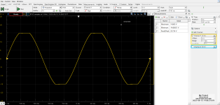
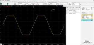
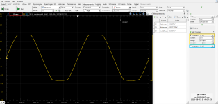
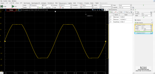
The confirmed circuit is shown in post #4, the input is 1kHz, 1.2Vrms,
To read the output DC level accurately, a probe (1:1, 1MΩ) is applied to the front of the coupling Co. The power supply voltage is adjusted to ±15.0V (±10mV).

It can be seen that the output headroom has a loss of approximately 1V on both positive and negative sides.
Just to be sure, I also tested it with a lighter load (Rf=18kΩ, Rg=2kΩ).

There is almost no change.
I checked the datasheet again I found the following notation:

Although the wording is not clear, I think it mean the loss voltage of output headroom from the rail voltage.
TI may have realized this mistake.
When the datasheet was revised due to the addition of OPA2828, the notation "RRO" was removed.

However, the web page is still marked as "RRO".
For comparison reference, the waveforms of RRO type OPA1611, 1641, 1655, ADA4625-1, and non-RRO type OPA627, 827, LME49710, ADA4627-1 are attached. (RL is the original 2kΩ.)
Compared to OPA627 and OPA827, OPA828 has improved headroom. However, there is a difference from rail-to-rail OP-AMPs.
I got OPA828 as soon as it was released, loved it, and have been using it for over four years, but I never noticed anything. (lol)
It seems that tombo56 also likes it and uses it, did you notice that?
but as I mentioned in post #9,
the distortion pattern of OPA828 differs from the rail-to-rail of traditional BB products, and the open-loop output impedance shown in Figure 25 of the datasheet is low and constant over a wide frequency range.Also, the main components of distortion are the low-order components of 3rdHD and 2ndHD.
This point is also different from conventional RtoR output such as OPA1611/1612.
I thought that was strange for as a rail-to-rail (common emitters) output.
Apparently, OPA828 is not a rail-to-rail output.
The output of OPA828 looks like a typical emitter follower.
I only noticed this after checking RickTH's post here.
The confirmed circuit is shown in post #4, the input is 1kHz, 1.2Vrms,
To read the output DC level accurately, a probe (1:1, 1MΩ) is applied to the front of the coupling Co. The power supply voltage is adjusted to ±15.0V (±10mV).
It can be seen that the output headroom has a loss of approximately 1V on both positive and negative sides.
Just to be sure, I also tested it with a lighter load (Rf=18kΩ, Rg=2kΩ).
There is almost no change.
I checked the datasheet again I found the following notation:
Although the wording is not clear, I think it mean the loss voltage of output headroom from the rail voltage.
TI may have realized this mistake.
When the datasheet was revised due to the addition of OPA2828, the notation "RRO" was removed.
However, the web page is still marked as "RRO".
For comparison reference, the waveforms of RRO type OPA1611, 1641, 1655, ADA4625-1, and non-RRO type OPA627, 827, LME49710, ADA4627-1 are attached. (RL is the original 2kΩ.)
Compared to OPA627 and OPA827, OPA828 has improved headroom. However, there is a difference from rail-to-rail OP-AMPs.
I got OPA828 as soon as it was released, loved it, and have been using it for over four years, but I never noticed anything. (lol)
It seems that tombo56 also likes it and uses it, did you notice that?
Attachments
-
 OPA1611_OUTPUT.png33.6 KB · Views: 235
 -
 OPA1641_OUTPUT.png33.6 KB · Views: 229
 -
 OPA1655_OUTPUT.png33.7 KB · Views: 223
 -
 ADA4625_OUTPUT.png33.6 KB · Views: 213
 -
 OPA627_OUTPUT.png33.2 KB · Views: 221
 -
 OPA827_OUTPUT.png33.3 KB · Views: 213
 -
 LME49710_OUTPUT.png33.4 KB · Views: 202
 -
 ADA4627_OUTPUT.png33.1 KB · Views: 218
Hi all, I have been using OPA627 in a CD player I/V stage after the DAC chip (TDA1541A) as an upgrade from the original NE5534 and I liked it. Now I purchased a pair of OPA828 and mounted them on SOIC/DIP adapter PCBs. I will try them in the same position as the '627. Has anybody any experience with them, what shall I expect?
The 627 is Class-A biased by a 1.5k resistor between the output and -Vcc, is there any benefit for the 828 if I keep this?
My other question is likeliness of parasitic oscillation. Is a WIMA 0.1u/63V MKP (or MKS?) capacitor between pins 4 and 7 sufficient for preventing oscillation?
Listening test will happen in the coming days, I just wanted to know the opinion of those who tried it.
Since it's a 45MHz device, 0.01uF to 0.1uF ceramic NPO/COG is best for decoupling,
with short leads, mounted on the adapter board.
with short leads, mounted on the adapter board.
interesting thread and good measurements - thank you therefore.
check out in this case this thread:
https://www.diyaudio.com/community/...st-possible-thd-n-really-the-best-way.367692/
and the question in post #2
As is well known, determining the THD value with a 1 KHz sine wave signal is useless as a benchmark for good sonic performance both on power amplifier devices and op amp integrated circuits.
Thus It was already a step in the right direction to increase the frequency therefore up to 20 KHz.
However, since music signals are not suitable for measurement purposes, I think it makes sense to extend the measurement frequency for the sinus signal much more further outside the audio range - I would say between 100KHz and 300KHz. And for IM measurements a two tone sine wave 199KHz+200KHz.
All discretely designed amplifier circuits on a virtual level (CAD software "circuitmaker"), which I also measured virtually by "circuitmaker" and produced a result with values in general on this choiced frequencies (which was often unsuccessful due to various error messages, especially with all circuits with more than one voltage gain stages in the NFB loop), had excellent sonic performances by check the circuit in real live.
Most of the circuits from Nelson Pass are also included, including discretely simplified circuits of the AD817 or AD825 (folded cascode + buffer - means only one voltage gain stage in the NFB loop)
Most design engineers for audio circuits consider this to be complete nonsense, arguing that the human ear has no perception at all in this area.
I see it differently - in my opinion one have to go so high in the measurement frequencies in order to get a better match between subjectively perceived good sound properties and the objective measured values, which at these frequencies only occur in a few cases (i.e. in a few power amplifier devices and integrated op amps) can be considered good.
Furthermore, even at these frequencies, it is important that the character of the residual distortions (fundamental notched out) must not have a triangular/sawtooth character and that no needle pulses must occur.
If only sine wave character on residual distortion is to observe, values 1-3% THD and below are inaudible or at least not annoying during listening tests.
Last edited:
- Home
- Design & Build
- Parts
- OPA828 / OPA2828 vs OPA627