Hello all, just attempting to keep the development of this sub uncluttered of the original dual PR system and keep away from the runaway robot head. The speaker is meant to be used laying down. Providing sequenced electronic kick as well as electric bass guitar support to an ensemble with folk instruments performing seated on the floor. The other role will be porch disco and home studio bass monitor
The design uses structural PVC foam as the core in a sandwich process. With the development of this cab, I am porting race boat construction tech to speaker cab design. This is also an attempt to model in a complete product using the FreeCAD program. The design exploits CNC and 3D printing tech to move away from the difficult process of the boat construction
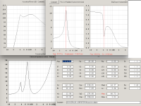
The physical constraints for the cab is 300mm x 300mm x 202mm, excluding any fabric or other trim parts. The volume to work within is 17L. The chosen high power driver models well at 6L with a flat response and sufficient SPL for the job. The excursion for both the active and PR drivers look decent to my inexperienced eye. The WinISD file is attached. Target is flat to 40hz, let's see if the proof of concept build delivers
Link to the active driver
https://ds18.com/cdn/shop/files/ZR6...-bf3e-d51fd6dfafb1.pdf?v=11627584538227543164
Link to the passive radiator
https://www.wagneronline.com.au/attachments/Audio-Speakers-PA/sbacoustics/SB15SFCR-00.pdf
WinISD screen capture, no filters. SBA 50g tuning weight for PRs applied. 6L driver working volume

FreeCAD Base body for the model

The design uses structural PVC foam as the core in a sandwich process. With the development of this cab, I am porting race boat construction tech to speaker cab design. This is also an attempt to model in a complete product using the FreeCAD program. The design exploits CNC and 3D printing tech to move away from the difficult process of the boat construction
The physical constraints for the cab is 300mm x 300mm x 202mm, excluding any fabric or other trim parts. The volume to work within is 17L. The chosen high power driver models well at 6L with a flat response and sufficient SPL for the job. The excursion for both the active and PR drivers look decent to my inexperienced eye. The WinISD file is attached. Target is flat to 40hz, let's see if the proof of concept build delivers
Link to the active driver
https://ds18.com/cdn/shop/files/ZR6...-bf3e-d51fd6dfafb1.pdf?v=11627584538227543164
Link to the passive radiator
https://www.wagneronline.com.au/attachments/Audio-Speakers-PA/sbacoustics/SB15SFCR-00.pdf
WinISD screen capture, no filters. SBA 50g tuning weight for PRs applied. 6L driver working volume
FreeCAD Base body for the model
Attachments

The displacement of the PR at Xmech (hard mechanical limit, suspension stretched to the limit, 62grams or more with added mass coming to an abrupt, noisy stop) is under that of the driver's displacement at Xmax (linear excursion), the PR 11x178=1958, driver 15x143=2145.The excursion for both the active and PR drivers look decent to my inexperienced eye.
A pair of those PRs is still less than double the displacement of the driver, a bit on the "light" side, unless you are not planning to use the full potential of the driver.
Your WinISD screen capture only indicates one PR:
Using two PRs will change the response considerably from your present sim.
Last edited:
Art, thanks man. Things like this helps me build some context. Now the above sim is with the driver at 600wrms of input power. The driver is only rated 300wrms and 600w peak. I know it can handle music of a 600wrms amp just fine but do not know if I can push it further. PR excursion shows as 7mm max at resonance and drooping either side with the active given 600wA pair of those PRs is still less than double the displacement of the driver, a bit on the "light" side, unless you are not planning to use the full potential of the driver
It does but the hump over 60hz? Is this the desired response curve over the single PR? Dual PRs also bring robot head back.Using two PRs will change the response considerably from your present sim.
Not sure if "above sim" is post #1 with one PR, and you have not posted what the driver's excursion is on either side of Fb. If the driver won't reach Xmax above Fb at max power, the net volume is too small.Now the above sim is with the driver at 600wrms of input power. PR excursion shows as 7mm max at resonance and drooping either side with the active given 600w
The hump looks like Fb is at ~65 Hz.It does but the hump over 60hz? Is this the desired response curve over the single PR? Dual PRs also bring robot head back.
Fb at the Fs of the driver (65Hz) will give the most output.
Lowering the Fb of two PR in such a limited volume would require way more added mass.
If you were happy with the response and output level in post #1 with the driver and PR output limited by cabinet volume, good enough.
Hasta,
Art
That’s correct re the “ above sim”. Active driver excursion is unremarkable so didn’t post pics. Well below 30% xmax at peak power rating. Seems well damped but as I always say, I may be reading improperly
Thank you for responding to my questions. Allow me to clarify some goals for this project. Firstly, I am using this driver model in a number of projects to trial it as a very compact and powerful bass monitor rather than a true subwoofer. These are space critical uses where the cabs have the listed constraints
In this case, pun intended, it has to fit under a stand holding a digital mixer. The stand is at floor seated ergonomics as the mixer is played like an instrument. The cab also needs to isolate and contain all the amplification and DSP electronics. That 17 odd litres is the space under the stand for all of that
Average floor mat is around 6m x 3m and there may be a ring of benches
The cab needs to deliver very short and dry kicks very fast soca music style electric bass guitar. The loudest instrument on the floor is the Dholak and the sub needs to match that SPL. As a comparison, a single Logitech Z623 is currently providing that mixer and bass monitor support to the floor and able to go toe to toe with the Dholak. Performers are seated in a ring
If there is a larger audience, a full PA is used. This the all that happens anyway unless I am covering the event. As far as I know, I am the only one who has a floorplay monitor system
Any suggestions on increasing output but keeping monitor grade response within the constraints?
Last edited:
Maybe I am doing something wrong. I have been running the sim though various volumes from 6L to 14L with single and dual oval PRs and various weights. The 6L with 50g on a single PR seems to be the flattest with usable reach down to 40hz. I found this to be the case when running ported sims. 40hz tune with 6L gave the flattest response. I would really appreciate it if someone would verify this. The WinISD file is attached to the first post in .zip
Art, I'll make a 10" active driver version of this cab after this project is tested. That will be built as a bass and synth amp with the HF drivers integrated
Art, I'll make a 10" active driver version of this cab after this project is tested. That will be built as a bass and synth amp with the HF drivers integrated
As before, I have created a hollow base body and modelled the sandwich lamination schedule on the inside faces of the curved panels. 1mm outer skin, 9mm PVC structural foam core and 1mm inner skin. The elements hierarchy can be seen in the left pane. It takes only one sketch to get to this point, where the sides are now complete. The active driver will go on the front panel and the PR on the narrower rear panel. I'll create these next


Front and sides in place. Complete lamination schedule and trims modelled in. Every thing is spot on for any further work in this area, and workarounds for FreeCAD limitations encountered in previous false starts all implemented in the three sketches and buildup to get this far. The active driver baffle and its trims are modelled in for bamboo and TPU. Bamboo for unidirectional fibres in the plank. Chosen for stiffness to weight thingys and fastener retention. This is the transom and engine mount. Load lines are figured in and run out to the front corners, then backwards down the tightening taper of the cab to a cushion which would be the PR on the back panel. Load lines from the driver also directly run backwards along parallel stringers inside the curved side panels and also follow the tightening cab taper. Note about driver load lines, in this build, they can be seen bounded by the inside fillets. These fillets won't taper as they move backwards, and also setup to work like wall brackets with a triangular truss or brace
This is one of the two jobs these fillets are getting broader FreeCAD limitations pre-dialed in for. The other purpose is an advanced batten that bridges two flat panels. These run load lines along their inside radius to create a box with panels. Unlike furniture making, these 'battens' are part of the body in a system called monocoque
Next up is the active driver cutout. The PR cutout will allow the active driver to be inserted into the cab and mounted from behind. Since I wanted greater than flush mounting depth to make space for cone excursion, fitting the driver from behind the panel will let me do that without making the panel too thick. An added benefit will be the clean cosmetic touch with no fasteners visible
Anyway, here is the work so far. I am very pleased with it and feel it's going to be a keeper. Next will work on drawing in the implementation for the above ramble into the model

A closeup of that top left corner showing the exacting work with the lamination and trim modelling, This including the curved laminates are all only using three of the simplest kind sketches

This is one of the two jobs these fillets are getting broader FreeCAD limitations pre-dialed in for. The other purpose is an advanced batten that bridges two flat panels. These run load lines along their inside radius to create a box with panels. Unlike furniture making, these 'battens' are part of the body in a system called monocoque
Next up is the active driver cutout. The PR cutout will allow the active driver to be inserted into the cab and mounted from behind. Since I wanted greater than flush mounting depth to make space for cone excursion, fitting the driver from behind the panel will let me do that without making the panel too thick. An added benefit will be the clean cosmetic touch with no fasteners visible
Anyway, here is the work so far. I am very pleased with it and feel it's going to be a keeper. Next will work on drawing in the implementation for the above ramble into the model
A closeup of that top left corner showing the exacting work with the lamination and trim modelling, This including the curved laminates are all only using three of the simplest kind sketches
Last edited:
Working on the back panel now. This will also be a manufactured bamboo plank with unidirectional fibres. And will also be scarfed with the outer skins. The slot that I just created for this panel can be seen in the pic below. The PR will fit into this as well as the I/O will be placed on the back
I have built in an allowance for a forward and rear face trim or veneer over these two bamboo panels. The finish for these can be just the bamboo look or a trim face up to 5mm thick. I will prolly use a 3mm thick decorative face here

I have built in an allowance for a forward and rear face trim or veneer over these two bamboo panels. The finish for these can be just the bamboo look or a trim face up to 5mm thick. I will prolly use a 3mm thick decorative face here
The back panel or PR baffle in place. Shaped piece of bamboo plank captured again by the outer skins. Again there is a 5mm allowance for any face trims

A temp cutaway to show the main stringer in place. This is also done in sandwich laminate layers. The next pic shows the fore, aft and stringer elements in place. Next job is filleting the stringer in


What would be top side for an upright or left for laying down. Again in the sandwich layers with the top skin covering all. The next pic is of the bottom or right if laid. Here is also a sandwich panel but this time the outer skin is not installed as a compartment will be built here. This will form the electronics bay for this project. In the satellites (Cubs), the outer skin will be a cosmetic slice. This compartment can be used in a non PR build as a port


Today, I made a different type of progress with this development. I kept thinking that I want to get to the stage of working on the internal structure without using as many elements as I had been using so far. So I revisited the sketches and refined them further, managing to drop quite a few elements along the way. Now the list in the left pane is a lot shorter and presents less load on my PC. Also optimised the whole design at the same time to make it even more CNC and final assembly friendly
Made another progress today. I have another project in progress, the mini table saw. I had been thinking about adding a mini router to the sliding table system and been sorting out details on that. I realised that I have come up with a viable mini router! Lots of folks have reported feeling uncomfortable with using a regular router, and I can understand this. It can be a scary machine to use and can be easy to make mistakes damaging the stock
I like how the mini router design will scale down the scary levels and allow less opportunity for mistakes with a lot lighter and easier to stabilise tool with a slower action. I need to fabricate parts but looks promising
I must say that I am very happy with my achievements with FreeCAD considering that I am at learner level and can be considered uneducated being a high school dropout and not being able to keep up with most discussions on here re acoustic and electronic engineering. Very glad to be able to have some area of knowledge to offer back to the forum where I am learning a lot and have received considerable assistance in many matters
All the forward planning and refining worked. All the inner seam fillets created to my determined sizes. Now this is a model of a monocoque vessel ready to be completed as an active or passive sub with PR or port or an active or passive FR or two-way with a PR or port for drivers up to 7 inches. I will now prepare this as the subject of the project, a 6.5" active bass monitor/sub containing amplification for 2.1 channels as well as the DSP and such electronics. 600wrms for the subs and 150wrms x 2 for the mains, using Erica.C's FFA001 and FFA002 class d modules

The Logitech Z623 sub maxes out around 105dB (indoors), the pair of 2.5" top speakers may not meet that SPL at 1meter ~200Hz.The cab needs to deliver very short and dry kicks very fast soca music style electric bass guitar. The loudest instrument on the floor is the Dholak and the sub needs to match that SPL. As a comparison, a single Logitech Z623 is currently providing that mixer and bass monitor support to the floor and able to go toe to toe with the Dholak.
An un-amplified acoustic bass or guitar can do similar SPL as the Logitech Z623.
Drums can typically play 10 or more dB louder, the Dholak player may be matching your Logitech Z623 level toe to toe "as the mixer is played like an instrument".
I don't use WinISD, so can't look at the file.Maybe I am doing something wrong. I have been running the sim though various volumes from 6L to 14L with single and dual oval PRs and various weights. The 6L with 50g on a single PR seems to be the flattest with usable reach down to 40hz. I found this to be the case when running ported sims. 40hz tune with 6L gave the flattest response. I would really appreciate it if someone would verify this. The WinISD file is attached to the first post in .zip
I'm not 100% certain all the driver TS parameters that could affect "flatness" are correct in my Hornresp simulations, but can say with certainty that the single PR output at 11mm Xmech around 40Hz will be no more than ~97dB, and dual PR +6dB,~103dB. Above that level, the PR will make popping sounds.
The dual PR may not have any more output than the Logitech Z623 sub's port, the single PR probably less.
The driver would only require ~50 watts to overdrive the single PR, and ~140watts to overdrive the dual PR, which would require 140grams of added mass to reach ~40Hz Fb in 6liters.
I don't know if the PR suspension would support that much additional mass, but the response shape wouldn't change:
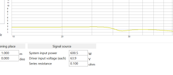
Tuning the driver for a "flat" bass reflex response in 6L (+3.15L for the port) will hit ~115dB at ~600watts, and even at 40Hz would have almost as much output as the PR:
Lower FB will reduce LF output, and the port diameter must be reduced to avoid too much cabinet volume:
Port velocity is rather high at those levels, but would keep the driver (and your toes..) cool 😉
Art
Attachments
Last edited:
I am now confused. In the previous thread, I halted the dual 8" and 10" PR v3 iteration before even starting after you pointed out that the active drivers would barely make them move. Now dual 8"x5"s would get overdriven at only 140w? What am I missing?The driver would only require ~50 watts to overdrive the single PR, and ~140watts to overdrive the dual PR, which would require 140grams of added mass to reach ~40Hz Fb in 6liters.
How reliable are these WinISD results?
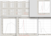
For single racer PR with 600w input
Active driver excursion with 600w input
SPL with 600w input
Tuning the driver for a "flat" bass reflex response in 6L (+3.15L for the port) will hit ~115dB at ~600watts, and even at 40Hz would have almost as much output as the PR:
Let's go back a few months to the "is this a BR or TL" and the Tiny 40s threads. This driver, when presented in a 6L with a flat 40hz tune. Do you recall how this was pointed out as being both a bad BR and bad TL? Issues with aspect and port length and pipe resonances and so on? That concluded with the recommendation that I should try PR instead
Trying to make sense of where I am at now. Should I drop the racer PR and go back to developing a DIY 8" and 10" custom PRs and the v3 cab or is the recommendation to drop the PRs and go back to the BR with the long port?
Again, how reliable is that WinISD sim? I would have thought that Hornresp would reproduce those same results, but something is off here
Attachments
@weltersys
Art, an excerpt from the datasheet. The only thing that matches your input parameters is the SD at 143. Am I reading this right? With so much variance, is your sim valid?

Art, an excerpt from the datasheet. The only thing that matches your input parameters is the SD at 143. Am I reading this right? With so much variance, is your sim valid?
A difficult position. I have been proceeding with the project with the belief that my WinISD sim is valid. I can't pick any data entry errors. Would really appreciate it if someone would help go over the WinISD sim attached in post and help troubleshoot that
I tried to run a Hornresp sim, but had trouble entering the data. As an example, the Cmp figure for the PR, I am unable to figure out how to enter this
I tried to run a Hornresp sim, but had trouble entering the data. As an example, the Cmp figure for the PR, I am unable to figure out how to enter this
SpeakerBoxLite
Ran a sim in this with the PR not wearing any additional tuning weight. Couldn't see how to apply 50g tuning weight. The red trace is 6L, green, 10L and blue 12L box volumes. I don't know, this seems like with the 50g add it will tune lower and is showing higher SPL for 6L than WinISD. Seems to accept parameters in the same format as the datasheet, so not too many places for confusion. I doubled the Re as want sure on this one with the DVC driver being driven by 2 channels of amp with one channel per coil
To my untrained eye, both WinISD and SpeakerBoxLite show promising results while I can't even figure out how to enter things correctly in HR, but Art is showing pretty sorry results in that
Recommendations?
- Home
- Loudspeakers
- Subwoofers
- Cub Sandwich PR Racer, floorplay sub