Clearly it depends upon your goals.
If your goal is to drive a 4 ohm loudspeaker and supply it with 10 watts RMS, then that circuit will be inferior.
On the other hand if your goal is to build a unity gain amplifier with input impedance > 40K ohms, and whose input voltage swing is less than +/- (Vrail - 4) volts , and which processes input signal frequencies less than 44 kHz, and drive a load resistance greater than 600 ohms, then many audio people would say that circuit will achieve some amount of success.

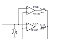
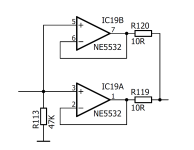
Is this a valid op amp circuit?
No. The slightest difference between the offset voltages will lead to one op-amp going into current limiting and the other trying to control the output.
With ideal op-amps it would be what my former network theory professor would have called a forbidden network, as it would have an uncountable infinity of solutions.
You would certainly be better off with unity gain buffers that each feed a balancing resistor.
No "shared" feedback.
No "shared" feedback.
parallel opamps with shared feedback
with unity gang.
most would say no go.
Feedback is after the current sharing resistors.
In simulation this usually cures the DC offset /standing current
or voltage war etc etc and other stuff people make up
for parallel opamps.
Does well usually in sim, shared feedback after current sharing resistors actually fixes the so called issues. But that is sim.
real life cure is just use
a single opamp that can supply 100ma of current.
Since there is plenty of them. Many with heatsink pads
for reliable operation over life time
Indeed.My concern is the fixed same feedback. right?
Regular opamps do always require individual feedback loops.
Only when the open-loop gain is very low (like 20dB max) and extremely well defined one can use a common feedback.
Only when the open-loop gain is very low (like 20dB max) and extremely well defined one can use a common feedback.
was that network professor mr Buijze? who managed to create a voltage gain using passive components. he called it resonance. no need to read elektor magazine and buy transistors...
Neerhoff taught network theory at the TU Delft in the late 1980's and 1990's, when I was there. He was rigorous and eccentric and very good at explaining network theory.
Absolutely not - you can never parallel inputs like that as the variation input offsets gets multiplied by the massive open-loop gain, saturating the two outputs at opposite rails.Is this a valid op amp circuit?
Perhaps this is based on a comparator circuit though? NE5532 will not function as a comparator as the inputs are tied together with diodes to prevent degrading of its low-noise input transistors.
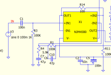
I've seen this used in headphone amps to increase op-amp gain. I have played with such circuits with Spice sim extensively and my conclusion is a better result, for me, is achieved with NJM4580 with its 50mA output. This let's me drive power transistors without drivers. I've attached a screenshot of my circuit - channel A buffered and channel B driving. NJM4580 can be found in dual channel single line profile - two SIPs can be inserted neatly in 16pin socket.
Attachments
not sure why many network theory professors are eccentric. Must something to do with what they teach.
Agree, they might fight each other, and the 10-ohm resistors might not be a good enough referee.No. The slightest difference between the offset voltages will lead to one op-amp going into current limiting and the other trying to control the output.
With ideal op-amps it would be what my former network theory professor would have called a forbidden network, as it would have an uncountable infinity of solutions.
not sure why many network theory professors are eccentric. Must something to do with what they teach.
I'll never forget Neerhoff's explanation of the response of an LRC parallel network with nonzero initial conditions (without excitation). First he just calculated the response, then he came with an intuitive explanation of the result. He explained that without the resistor, the C would pass its energy to the L, the L to the C, the C to the L and so on until infinity, as they are both lossless. But the resistor could only absorb energy, not give it back. That energy would be dissipated, converted to non-electric energy forms,
met andere woorden, die weerstand die zegt hap, en de energie die is pleite. In de volgende halve periode zegt de weerstand weer hap, de energie die is weer pleite, daarna zegt hij weer hap, de energie die is weer pleite en zo krijgt men een exponentieel uitdempende, sinusvormige kromme.
Poor translation:
in other words, the resistor takes a bite, and the energy is gone. In the next half period, the resistor again takes a bite, and the energy is gone again, then it again bites, the energy is gone again and that way, one gets an exponentially damped sinusoidal curve.
- Home
- Source & Line
- Analog Line Level
- Valid opamp circuit?