The Jackson is my first tube tester. I just bought it at auction for $20 and it works!
I need to test several 829b tubes and of course it has no 7-pin socket or testing parameters for the 829b.
My "logic" is to fabricate a pair of octal to 7-pin adapters and then select a pentode from the Jackson's parameter list which seems most similar to half of the 829b for testing:
I need to test several 829b tubes and of course it has no 7-pin socket or testing parameters for the 829b.
My "logic" is to fabricate a pair of octal to 7-pin adapters and then select a pentode from the Jackson's parameter list which seems most similar to half of the 829b for testing:
- a pair of sockets to test half the tube at a time
- The curves for the 6L6 look very close
- the objective is not accuracy in testing, but balancing of tubes, so use of similar tube parameters should work in spite of not providing results
- are there pentodes closer in performance parameters to one segment of the 829b than the 6L6?
- is a pair of adaptors overkill? could I just fabricate one adaptor and move the anode connecter from one side to the other to test each element?
I would purchase a B7A valve base and a blank Octal pug, marry the two together to emulate a 6L6 for the wiring adding a change over switch between the anodes.
These have a much lower anode - cathode voltage than the 6L6. 250 volts if memory serves me correctly.Tie the control grids together and everything else is ready.
These have a much lower anode - cathode voltage than the 6L6. 250 volts if memory serves me correctly.Tie the control grids together and everything else is ready.

Also be careful. The screen grid and cathode are common, if you only connect one anode you may burn the screen grid of the other section. The good thing is that the heater is centre tapped, you can power just one heater section at the time.
If the control grid is biased off, on the side not being tested, the screen grid will not conduct.
I was warning about the situation, and the above advice.Tie the control grids together and everything else is ready.
So the conclusion is that I need two adaptors, each powering only one side of the heater and only one anode?
Or is the conclusion that I must test both sides at once?
Or is the conclusion that I must test both sides at once?
- If so the single meter in the Jackson will display the sum of both segments.
- This would drive the meter to 200% with 6L6 parameters, (and the meter pegs at 130%) so I will need to select parameters of a different tube. Any suggestions?
Is the possibility of burning the other screen grid mitigated if the tube is tested in "triode mode", with the screens strapped to the anode?
What I would do (and what I did) is to insert a 1 or 10 ohms resistor in series with each anode, so it is possible to measure each section easely.
I always want to measure both halves. I would build an adapter with a switch to select the heater section. One thing to be careful is never operate SW1 when the tube is hot and powered. Start from cold, measure one half, turn off, let the tube cool down, 5 min to be safe, then switch to the other half, power on and measure again.

If you don't have access to a purpose built tube tester like an Avo or one with similar capabilities then you could rig up a basic test circuit with HT supply for the anode and G2 and a variable bias supply for G1 and note the anode current at a certain bias point - do this for each tube and compare, if the tubes are a close match the anode currents should be close to each other, if you need to check the Gm just vary the bias by 1 volt and note the change in anode current.
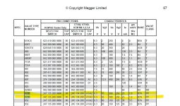
I attached a screen shot from the Avo tube tester data manual, it shows suggested voltages used for testing.
I attached a screen shot from the Avo tube tester data manual, it shows suggested voltages used for testing.
Attachments
- Home
- Amplifiers
- Tubes / Valves
- new Jackson 648a tube tester and 829b tubes to be tested