nerdorama,
Good Idea!
Thanks for Sharing, more people need to know about that.
A re-stacked push pull transformer.
I too mentioned it many times in many threads, even once last week.
You said:
"At 1W it measures -3dB at 15Hz and 65kHz"
What were the major factors for the roll off at 15Hz?
Plate Choke?
Output transformer inductance (even with the advantage of having the E's and I's all interleaved)?
RC coupling network from driver to output tubes?
6V6 in pentode mode
Other?
Example:
3 each -1 dB single ended poles at 15Hz = -3dB at 15 Hz.
RC coupling, plate choke, an output transformer that each are -1dB @ 15Hz gives a total of -3dB @15hz
Looks like there are mistakes. But cannot say for certain. Their definition of cathode feedback ratio is also funny. The normal definition is either ohms or percentage of primary turns. I guess the marketing people are putting those specs out and they don't have a real understanding of what they sell.One thing bugs me about their new CFB P-P toroidals, they all seem to have the same primary according to the Toroidy stats. Seems like that would run out of voltage headroom for the higher Z OTs ? I can only surmise fewer turns on the secondary for higher Zprimary ? Normally one expects the secondary to stay the same (for same core size) and the primary turns to increase for higher Zprimary. (all same 80 Watts)
Loudspeakers and even the woofer alone do not behave ideally or symmetrically too. Their behaviour is highly signal dependent and is not not really linear even at fixed (fairly higher) signal level (think about the force factor asymmetry which is ALWAYS present to some degree, for example). You can see that in stationary conditions the T&S parameters at low and high signal level are not the same. Then add the actual acoustic load (that in most cases is not symmetric at all) and it is possible that having an asymmetric DF is not necessarily bad.I. Generalizations of Both single ended and push pull amplifiers that do not have negative feedback:
Single Ended Amplifiers:
Everybody remembers the fact that most single ended amplifiers have dominant 2nd Harmonic Distortion.
And, that when the amplifier is only putting out a small portion of its maximum output power, Distortion is at a Very Low percent (%).
But what is too often forgotten about single ended amplifiers is their Damping Factor Characteristics:
A. When the amplifier is only putting out a small portion of its maximum output power, The Damping Factor often is Medium, and is Symmetrical.
B. When the amplifier is putting out its maximum output power, The Damping Factor often is Low, and is Very Un-Symmetrical.
So,
Think about how the loudspeaker woofer responds to the amplifier's Symmetrical Damping Factor (A.),
and then how the loudspeaker woofer responds to the amplifier's Un-Symmetrical Damping Factor (B.).
Symmetrical Damping Factor at low power levels (Class A), but Un-Symmetrical Damping Factor at high power levels (Class A, single ended must stay in Class A, or the music sounds very bad because of the clipping).
Push Pull Amplifiers:
Everybody remembers the fact that most push pull amplifiers have dominant 3rd Harmonic Distortion.
And, that when the amplifier is only putting out a small portion of its maximum output power, Distortion is at a Very Low percent (%).
What is too often forgotten about push pull amplifiers is their Damping Factor Characteristics:
A. When the amplifier is only putting out a small portion of its maximum output power, The Damping Factor often is Medium, and is Symmetrical.
B. When the amplifier is putting out its maximum output power, The Damping Factor often is Medium, and is Symmetrical.
So,
Think about how the loudspeaker woofer responds to the amplifier's Symmetrical Damping Factor (A.),
and then how the loudspeaker woofer responds to the amplifier's Symmetrical Damping Factor (B.).
Symmetrical Damping Factor at all power levels (Class A).
Having a lower DF often results in cleaner and faster impulse response! It's not intuitive but that's one of main advantages of current amplifiers (i.e. very small DF, ideally zero). Loudspeakers have their own self-damping which is normally the main one and because they do not behave linearly if one attempts to damp the motion with the amplifier the result is actually worse in comparison to an amp with lower DF which in the end only causes an initial higher overshoot but extremely short in time and so less harmful.....
People worry a lot about +/-0.5-1 dB variation in the frequency response when using low DF amp but in reality they ignore typical loudspeakers' FR are heavily smoothed out and 0.5-1 dB is actually a tiny change. They worry much less about time domain which is actually the most important one.
Last edited:

@6A3sUMMER
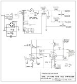
I can't answer all of your questions as I have no idea that reason for some of the issues. When I was planning this project it was suggested to me to consider parafeed. Matt was amenable and stacked the SE transformer as he would for a PP, i.e., alternating I's and E's without an air gap. I used a pair of 50H Bottlehead plate chokes. The project is on HiFiHaven and the plan belongs to others rather than me.
https://hifihaven.org/index.php?threads/sakuma-schade-6v6-amp.8961/
My project in the discussion begins around posts 189 and 192. This is the schematic for my amp. Paul B. was the instigator for the project.
Attachments
@nerdorama, removing the air gap also removes the main advantage of SE output transformer: the narrow and much more "linear" hysteresis loop. Parafeed is just more economical: cannot compare to a proper SE, cannot compare to good PP. The only way to get close to proper SE is to use exotic cores like nanocrystalline or mumetal that have a natural narrow "linear" hysteresis. You still have the additional CCS or inductance to feed the plate. If you use a choke that will be in parallel with the OPT and thus halving or even more decreasing the effective inductance. People are worried so much to solve the problem at 20Hz and below that they often don't realize that they have just made it worse in the octave just above where there is a lot more musical signal.....
nerdorama,
Thanks!
The schematic in Post # 44 is very interesting:
1. Uses Schade Negative Feedback, with the signal coming from the junction of the output tube's plate choke and the output tube's plate.
I had never seen this method used with a Parafeed output (Parafeed Plus Schade in the same amplifier).
2. Using a 6V6 as the input tube, quite unusual. It is wired in Pentode mode.
3. The 6V6 Output tube is also wired in Pentode mode.
4. Something to try if you want to:
Disconnect the output tube screen, pin 4, from the resistor and capacitor is is connected to in the schematic.
Then connect a 100 Ohm resistor from the output tube screen, pin 4, to the output tube plate, pin 3.
That will allow you to listen to Triode Wired Beam Power tube Mode.
Less Power, and Less Gain.
So why try that . . . to get Less distortion, and Higher Damping Factor.
That might not work real well because of the Schade negative feedback, so you can remove the 100k Schade negative feedback resistor, and try
Triode wired mode without Schade negative feedback.
5. An amplifier output stage that is -3dB @ 20Hz due to the inductance of the choke in parallel with the output transformer's inductance, will be -1dB @ 40Hz. Many electric Bass Guitars only go down to 41Hz.
My loudspeakers do not really work at 20Hz.
Have Fun!
I appreciate all the suggestions. The amp sounds so good to me that I'm leaving it alone. It has lower measured distortion than a series feed version, the bass is really good for an SE amp (I'm not generally a SE fan) and the treble is airy and detailed without any harshness. The pentodes with the local feedback are a feature not a detriment and have a composite behavior like a triode but with pentode power. The amp is only 3+ watts so I'm not much interested in triode mode for this amp and losing more power. Sorry.
all the best,
John
all the best,
John
Pentode +local feedback is the best option for me, too. If you get better results it's fine but it only means your series feed transformer was not good enough.
Which parameters would be considered "good enough"? Asking purely from curiosity as I have more experience with PP amps.
Typically OPT's for low power amps have poor inductance. You can guess that from their size because people don't want to put much money in it. That is usually the compromise for acceptable cost, efficiency and FR. For a PP amp this is not a problem because there is no gap and for the same power rating the core could be 4 times smaller or same size with a lot more inductance.Which parameters would be considered "good enough"? Asking purely from curiosity as I have more experience with PP amps.
As I said, if this project was just fun and you wanted to keep it cheap, your choice is fine.
@rdf, yes for me it's normally cathode fbk.
6V6 triode curves don't look all that great. 6V6 pentode curves do look pretty good. The Schade Fdbk is likely the winner there.
I should amend my comment about the KT88 back in post 37. I was looking at the JJ KT88 curves. The GEC curves for KT88 look much better.
I have seen plate curves that actually helped reduce the 3rd Harmonic Distortion in some push pull circuits (under certain quiescent voltage and quiescent current). But you will trade off something else for that . . . most often Output Power.
Tradeoffs, Tradeoffs, Tradeoffs.
You can't have it all.
Your Curves May Vary
Let me know where you can purchase NOS GEC KT88 tubes. They most likely are fake, not original from that many years ago.
Tradeoffs, Tradeoffs, Tradeoffs.
You can't have it all.
Your Curves May Vary
Let me know where you can purchase NOS GEC KT88 tubes. They most likely are fake, not original from that many years ago.
There is little point in using triode or UL if one can do pentode + local fbk (either cathode fbk or Schade fbk or plate to driver's cathode). The pentode + local fbk will always be more linear and more efficient.6V6 triode curves don't look all that great. 6V6 pentode curves do look pretty good. The Schade Fdbk is likely the winner there.
Having said that, lately I have also finished a small 2-stages PP amp with 2 PCL82s per channel: para-phase splitter + UL output into 9K a-a and 6 dB loop fbk. It sounds wonderful and makes a whopping 12W before seeing anything on the sinusoidal output.
Last edited:
I should add that JJ's KT77 pentode curves look pretty good (for AB1). Good in triode mode too.
But when I saw their KT88 curves, I thought something was wrong with their curve tracer. A big jump in gain at one curve.
Some old tubes with great pentode curves (for AB1): EL506 and EL508. Too bad they are extinct. The 10JA5 was a nice (not direct, lower Vg2 also) sub for EL506, but looks to be going extinct now too. 6LU8/6LR8 still around (same pentode). 6HB6, mostly gone, 12HL7 too. 38HE7 still around and good in triode too. (talking -cheap- linear AB1 pentodes here)
The 12HL7 pentode grid1 curves look as good as the grid2 curves. An amazing tube. Even -exceptional- in triode mode. Only 10 Watts though. Have to try some in parallel (with a diode to protect the high gm frame grid from +Vg1) Now that's a real sleeper for SE.
12HL7 in triode mode 1st pic: And 38HE7 in triode mode 2nd pic:
Last edited:
@smoking-amp which kind and brand of 12HL7 did you test in triode mode? I remember there are different constructions, if I am not wrong.
Last edited:
Sylvania designed the 12HL7. Some RCA versions have something else in them, a smaller assembly with poor curves.
I think Sylvania kept more space between grid1 and the cathode compared to similar tubes like 12GN7 and 12HG7 with their higher gm. The 12HL7 has "lower" gm than those two (still 21000 ! ). But was probably higher "yield" than the others (fewer g1 to k shorts).
I would check any such frame grid tubes on a curve tracer, since the smallest shipping "bump" could push the g1 off center from the cathode enough to mess up the curves.
I also wonder about the 10 Watt plate rating for 12HL7. The 12HL7 plate looks about the same as the 12BY7 6.25 Watt plate.
If one decides to derate the 12HL7 10 Watts to maybe a safer 7.5 Watts, then the 6197 7.5 Watt tube becomes competitive and it has a huge plate for a 9 pin tube.
6197 is a computer tube (similar to, but not the same as 6CL6), but sure looks good on the curve tracer:
.JPG")
.JPG")
I think Sylvania kept more space between grid1 and the cathode compared to similar tubes like 12GN7 and 12HG7 with their higher gm. The 12HL7 has "lower" gm than those two (still 21000 ! ). But was probably higher "yield" than the others (fewer g1 to k shorts).
I would check any such frame grid tubes on a curve tracer, since the smallest shipping "bump" could push the g1 off center from the cathode enough to mess up the curves.
I also wonder about the 10 Watt plate rating for 12HL7. The 12HL7 plate looks about the same as the 12BY7 6.25 Watt plate.
If one decides to derate the 12HL7 10 Watts to maybe a safer 7.5 Watts, then the 6197 7.5 Watt tube becomes competitive and it has a huge plate for a 9 pin tube.
6197 is a computer tube (similar to, but not the same as 6CL6), but sure looks good on the curve tracer:
Last edited:
- Home
- Amplifiers
- Tubes / Valves
- Consensus on the Hammond 1628SEA?