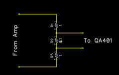
A pair of 8 ohm resistors gives options of 4, 8 and 16.
https://audioxpress.com/article/you-can-diy-build-an-audio-dummy-load
https://audioxpress.com/article/you-can-diy-build-an-audio-dummy-load

No, the resistor is not non-inductive. However, I see the same graph results with no load resistor (just my measurement box input impedance).
EDIT: The input impedance for my Scarlett Solo is either 3k, 60k, or 1M, depending on the input and mode. I measured my BA3 amp against it, and that was flat.
Yes, you need non-inductive dummy loads. The Pass amp may not be sensitive to an inductive load, but tube amps usually are.
@grovergardner Ahh, thank you for that tidbit! I was wondering why it wasn't an issue on the other amp.
I've ordered some resistors to make a load/voltage divider, like shown. That will let me run a higher input voltage.
(Image source: https://quantasylum.com/blogs/news/basics-power-amps)
(Image source: https://quantasylum.com/blogs/news/basics-power-amps)
Attachments
I'll be surprised if the dummy load resistor type makes a jot of difference. (you already proved this when you measured with no load)
If it does, then when the amp drives a speaker load, the response will be all over the place.
If it does, then when the amp drives a speaker load, the response will be all over the place.
Have you changed the feedback resistor?
If that was inductive, it would increase the gain with frequency......
I've never come across the way the OT secondary is connected....
If that was inductive, it would increase the gain with frequency......
I've never come across the way the OT secondary is connected....
Yes..
Someone said earlier that the secondary shoul not be connected to 0v and I agree, and also that to preserve symmetry, the speaker should be conneected between the 4 and 8r taps.
It would make more sense to me if the 8r tap was grounded and the speaker connected betweeen this and 16 or 0 tap (8r speakers)
Last edited:
Batteryman,
And others who are interested,
The D70 amplifier uses Balanced global negative feedback.
A secondary with 0 (common), 4, 8, and 16 Ohm taps, has the same number of turns from 0 to 4, as the number of turns from 4 to 16.
By grounding the 4 Ohm tap, the 0 tap and 16 Ohm tap put out the same voltage from ground, and that is in opposite phase.
Nice design idea to get Balanced global negative feedback.
But, you need to connect an 8 Ohm speaker from the 0 tap, to the 8 tap.
The difficulty comes when you want to Measure the D70 output voltage into an 8 Ohm speaker (or non-inductive load resistor).
Most scope probe ground clips are grounded (that is why they call them ground clips). That is for safety reasons.
Connect the probe tip to the 8 tap, but you need to measure from there to the 0 tap (and that is not grounded, but the scope probe ground clip is grounded).
How, to do that if you do not have a differential probe (expen$ive)
If you have a 2 channel scope, you can set one channel to Invert function, and do a Math Channel Add-function (many modern scopes have these functions).
Connect Both probe ground clips to the grounded 4 Ohm tap of the D70.
Connect one channel's probe tip to the 0 tap, and the other channel's probe tip to the 8 tap.
That is the poor man's differential measurement. Much better than guessing! And, it $aves Money.
When you are in the middle of the Pacific Ocean on a US Naval Destroyer, and do not have proper test gear, you figure out how to get the job done; such as the above solution.
Have Fun!
Thanks, that explains the OPT wiring.
As for the grounding issue.
Use a laptop and REW or similar. The psus aren't grounded, or otherwise run it on the battery.
As for the grounding issue.
Use a laptop and REW or similar. The psus aren't grounded, or otherwise run it on the battery.
batteryman,
If you measure the output signal of the D70 at the same time you use the same measurement equipment to measure the input signal,
You might short the output signal to the input circuit ground.
If you measure the output signal of the D70 at the same time you use the same measurement equipment to measure the input signal,
You might short the output signal to the input circuit ground.
You don't need to measure the input with REW, you can set it's output level in the software so there is only a two wire connection to the amp's OPT / load resistor so no problems that I can forsee?
You will need to use the 4r tap as the output ground, however. Just connect the dummy load between 4 and 8r taps as this is just for measurements.
You will need to use the 4r tap as the output ground, however. Just connect the dummy load between 4 and 8r taps as this is just for measurements.
Last edited:
I am not familiar with REW.
Can REW correctly graph out the phase of the output signal, versus the phase of the input signal?
Or do you have to use a channel to measure the phase of the input signal?
Can REW correctly graph out the phase of the output signal, versus the phase of the input signal?
Or do you have to use a channel to measure the phase of the input signal?
It does display the phase of input relative to output.
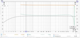
Example attached of my Cinese SE amp before mods.
(you first calibrate your sound card using a loopback lead so you can check the phase response) I use a Behringer UAC222. It's max in and out is about 2v rms so an attenuator is needed when testing amps..
Example attached of my Cinese SE amp before mods.
(you first calibrate your sound card using a loopback lead so you can check the phase response) I use a Behringer UAC222. It's max in and out is about 2v rms so an attenuator is needed when testing amps..
Attachments
Last edited:
Yes..
Someone said earlier that the secondary shoul not be connected to 0v and I agree, and also that to preserve symmetry, the speaker should be conneected between the 4 and 8r taps.
It would make more sense to me if the 8r tap was grounded and the speaker connected betweeen this and 16 or 0 tap (8r speakers)
This is not at all correct. The ARC amplifier has partial cathode coupling, and symmetrical feedback from the OT secondary.
The 4 ohm taps are grounded. Symmetrical loading would be between the 0 and 16 taps.
Connecting a load between the 4 and 8 taps would be both asymmetrical and poor matching.
- Home
- Amplifiers
- Tubes / Valves
- What on earth have I done to my amp....