Amp: Audio Research D70 MkII
Background: I have been attempting to identify and replace resistors that are causing fuzzy output distortion. I have also disconnected the 16 and 4 ohm outputs, and wired a pair of modern binding posts to the 8 and 0 ohm outputs.
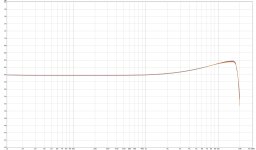
I discovered that somehow, the amp is now producing an upward curve starting around 1k and peaking at +4 dB at ~18k (see attached measurements, both channels). I have verified that this is not a problem with my measuring equipment by testing another amp. I'm taking measurements with a 7.5 ohm load resistor at 1v output level.
My first thought was that I screwed up a resistor value, but I've been careful about that, and I'm not necessarily replacing matching resistors on both channels if only one seemed bad, so how would I get identical behavior on both channels?
Second thought is that someone I crossed wires from the output transformer and created this effect? But I'm not sure how that would even work.
I'm on the verge of throwing it at my tech and having him pull my *** out of the fire, but I'd at least like to try fixing whatever I've done....
Background: I have been attempting to identify and replace resistors that are causing fuzzy output distortion. I have also disconnected the 16 and 4 ohm outputs, and wired a pair of modern binding posts to the 8 and 0 ohm outputs.
I discovered that somehow, the amp is now producing an upward curve starting around 1k and peaking at +4 dB at ~18k (see attached measurements, both channels). I have verified that this is not a problem with my measuring equipment by testing another amp. I'm taking measurements with a 7.5 ohm load resistor at 1v output level.
My first thought was that I screwed up a resistor value, but I've been careful about that, and I'm not necessarily replacing matching resistors on both channels if only one seemed bad, so how would I get identical behavior on both channels?
Second thought is that someone I crossed wires from the output transformer and created this effect? But I'm not sure how that would even work.
I'm on the verge of throwing it at my tech and having him pull my *** out of the fire, but I'd at least like to try fixing whatever I've done....
Attachments
There are global negative feedback signals from Both the Common Tap, And the 16 Ohm Tap.
Did you maintain those connections properly.
And, it is the 4 Ohm tap that is at amplifier signal ground.
Is the 4 Ohm tap Still connected to signal ground.
Refer to the schematic for the answers to the above.
Changing any of that Will cause a problem.
Restore the original connections.
Does that fix the problem?
Last edited:

I think you're right about the feedback loop. I thought I had accounted for it. But, I will go in again and verify, and probably determine I am wrong.
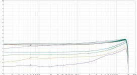
I've done some experimenting. The attached graph shows the results of connecting and disconnecting various feedback loops. Low gain is likely due to alligator clip connections. The best are when the proper feedback signals to 16, 4, and 0 ohm taps ("feedback signal" meaning "there is a wire that goes to the point specified on the schematic). The key element is that they all peak just before 20k.
Attachments
I did that.
EDIT: Well, the original connections were to a binding strip that’s no longer there. But I have connected the ends of the wires as they were when soldered to the binding strip.
EDIT: Well, the original connections were to a binding strip that’s no longer there. But I have connected the ends of the wires as they were when soldered to the binding strip.
Testing done under rated output loading, or open circuit?
Testing of the differential output done with a differential probe?
Grounding with test equipment of any output taps (other than 4 ohm) is prohibited.
The 0 ohm taps may NOT be connected to any ground.
Testing of the differential output done with a differential probe?
Grounding with test equipment of any output taps (other than 4 ohm) is prohibited.
The 0 ohm taps may NOT be connected to any ground.
Tests were done with an output voltage of 1.0v, requiring an input voltage of 0.075v. Tests were initially open circuit, but after you reminded me I put a 7.5 ohm resistor in as load, and observed no change in behavior.
Watching the input level meter in REW while it’s sweeping, it holds flat for most of the run, then rises at the end, along with an audible tone from the output transformer.
Watching the input level meter in REW while it’s sweeping, it holds flat for most of the run, then rises at the end, along with an audible tone from the output transformer.
Neither the 8 ohm nor the 0 ohm taps may be grounded. They are floating output nodes.
Does your test system connect either to ground?
Does your test system connect either to ground?
8 ohm is only connected to output
0 ohm is connected to output, and point 36, as specified in the schematic.
0 ohm is connected to output, and point 36, as specified in the schematic.
Update: 8 ohm to 4 ohm produces flat output. I tested all to 0 ohm and all to 4 ohm. No other combination produces a flat output.
I discovered that somehow, the amp is now producing an upward curve starting around 1k and peaking at +4 dB at ~18k (see attached measurements, both channels). I have verified that this is not a problem with my measuring equipment by testing another amp.
The other amp does not have balanced, floating outputs, does it?
Then that is not evidence that you are testing the ARC properly.
Is the proper load impedance connected to the proper output taps,
across both of which the test connections are taken?
Does your test system have two balanced, floating inputs?
If not, it cannot properly test this amplifier.
We are either Balanced in our measurement techniques
Or We are Un-Balanced in our measurement techniques
Def: Balanced. adj. Being in harmonious or proper arrangement, or adjustment, proportion, etc.
All measurements should be made like that.
For the discussion of this thread . . . the word balanced means more than the above definition, because we are talking about single ended measurements, verus balanced measurements.
With the 4 Ohm secondary tap grounded, you get two things:
1. Two phase negative feedback signals (an advantage that also has tradeoffs).
2. A much more complicated measurement setup; it has to be Balanced.
I tried the scheme of grounding the 4 Ohm tap, it was OK, and I was able to set up the measurements properly.
But I never used the grounded 4 Ohm tap again, I do not really like that method.
Last edited:
@rayma My reference amp has only single-ended inputs (is a BA3). The ARC amp has only single-ended inputs. My measurement devices is a Scarlett Solo. I am using single-ended output and input for generating and receiving the test signal.
I have used a 7.5 ohm load resistor for all tests
I'm not sure I understand this question. None of the devices in use are connected with balanced signals.
I have used a 7.5 ohm load resistor for all tests
Does your test system have two balanced, floating inputs?
I'm not sure I understand this question. None of the devices in use are connected with balanced signals.
No, the resistor is not non-inductive. However, I see the same graph results with no load resistor (just my measurement box input impedance).
EDIT: The input impedance for my Scarlett Solo is either 3k, 60k, or 1M, depending on the input and mode. I measured my BA3 amp against it, and that was flat.
EDIT: The input impedance for my Scarlett Solo is either 3k, 60k, or 1M, depending on the input and mode. I measured my BA3 amp against it, and that was flat.
Who the heck knows the details of a BA3 amplifier . . . not me.
Do not use an amplifier to validate your test equipment.
Some amplifiers have perfectly flat frequency response into 8 Ohms, and also have perfectly flat frequency response into an open circuit.
"All amplifiers are created equal, but some amplifiers are more equal than others" - with respective credit given to George Orwell's "Animal Farm"; but highly modified by me to illustrate something.
Purchase a proper non-inductive load resistor.
And . . .
An 8 Ohm full range driver is an inductive load at high frequencies.
It makes a very poor load for testing an amplifier, and those sustained sine wave test tones hurt your ears.
BA3 = Burning Amp 3 = Nelson Pass = This Community. I thought people would recognize the acronym.
I can get a better resistor. But:
If the resistor was the problem, why would I get this ~4 dB rise with one amp and not with another? If the fault was the resistor, shouldn’t it affect everything equally?
I used the BA3 because it’s a known quantity. I’ve measured its frequency response many times with multiple test setups.
I suppose I should get 4, 8, and 16 ohm load resistors then?
You just need a pair of 8 ohm resistors per channel.
Series and parallel for other impedances.
Series and parallel for other impedances.
- Home
- Amplifiers
- Tubes / Valves
- What on earth have I done to my amp....